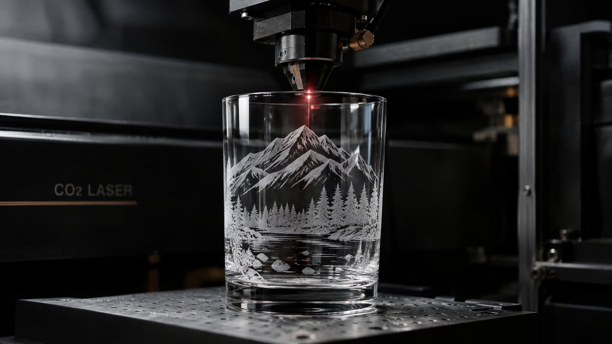
You copied the chart. You ran it line for line, and the glass came out patchy and chipped instead of cleanly frosted. That chart was never going to work on your machine, because it was tuned to someone else’s tube wattage, lens, focus height, and even their glass batch. What follows is wattage-tiered starting numbers for CO2 machines from 40W to 100W, the fracture mechanism that turns every settings rule into logic instead of memorization, and a test-grid procedure so you can dial in your own machine instead of borrowing someone else’s luck. One reframe up front, because it inverts beginner instinct: on glass, more tube wattage means running lower power percentages.
Key Takeaways
CO2 glass starting ranges span 100-300 mm/s at 30-50% power on a 40W tube down to 12-15% power on a 100W tube, where Neil (LaserCuttingPro) engraved an 800x800mm workshop window at 150 DPI and 250-300 mm/s in about 1.5 hours.
Glass “engraving” is actually micro-fracturing, not material removal, so multiple light passes with cooling between them beat one hot pass, and running faster produces a whiter, crisper etch with less chipping.
Diode and fiber lasers can’t mark clear glass directly because of wavelength limits, not power limits; the working paths are Tribo’s paper-backing back-engraving for diodes and the foil-and-paint prep method for fiber.
Table of Contents
Starting laser engraving glass power settings by CO2 wattage
For CO2 machines, workable starting ranges for laser engraving glass run from 100-300 mm/s at 30-50% power on a 40W tube up to 400-800 mm/s at 40-80% on a 100W tube, per Redsail’s glass etching guide published February 7, 2025. Here’s the full table:
| CO2 tube | Speed | Power | Frequency |
|---|---|---|---|
| 40W | 100-300 mm/s | 30-50% | 500-1000 Hz |
| 60W | 200-400 mm/s | 30-60% | not published in the source |
| 80W | 300-600 mm/s | not published in the source | not published in the source |
| 100W | 400-800 mm/s | 40-80% | 1000-2000 Hz |
Yes, the 80W row’s power value is missing from Redsail’s guide. I’d rather tell you that than invent a number that looks authoritative and isn’t. Cross-reference the 80W row against the other sources below and start low.
If you’re on an OMTech with a 60-100W tube, their manufacturer-backed spec is 20-50% power at 200-400 mm/s, with DPI 200-300 for simple text and logos and 400-600 for intricate designs. An OMTech 60W owner should be able to stop reading right here, run 200-400 mm/s at 30-60%, and be in business.
StyleCNC’s master settings chart makes a useful cross-check: their glass row puts an 80W CO2 machine at 350-450 mm/s and 15-20% power, with diode and fiber listed as incompatible. Their general conservative CO2 starting range is 300-500 mm/s at 12-25%, which sits comfortably below the Redsail percentages.
And here’s the proof that the low end isn’t a typo. Neil documented engraving an 800x800mm workshop window at 150 DPI, 250-300 mm/s, and just 12-15% power on a 100W tube, finished in about an hour and a half. A 100W tube, running at a fraction of what beginners assume is necessary, on a window-sized canvas. That’s the pattern in every one of these numbers: as wattage climbs, the percentage you run drops, since energy per point is what governs the result, not the sticker on the tube. Every value above is a starting point to validate on your own machine, not a guarantee.
Why glass cracks at high power: the micro-fracture mechanism
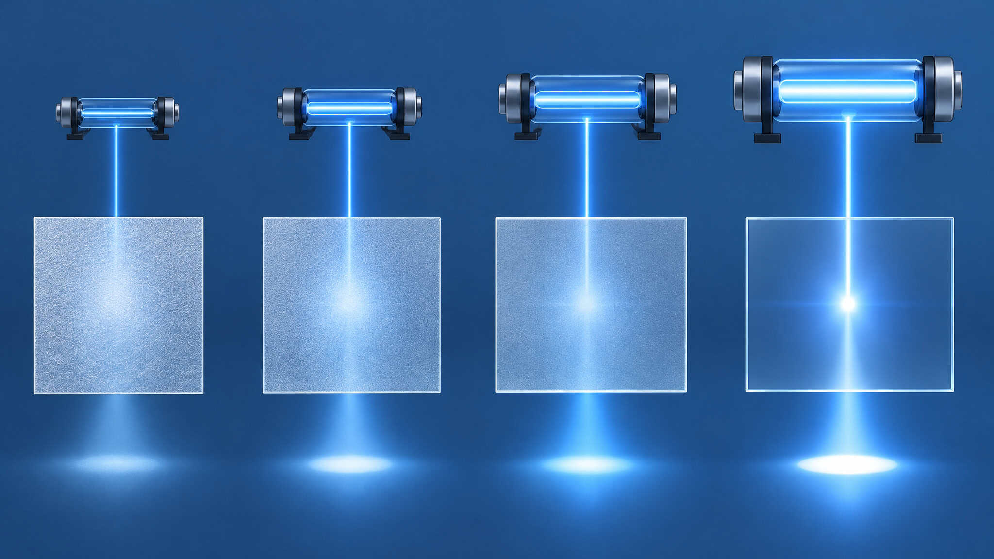
Glass cracks at high power because the “engraving” is fracturing. A CO2 laser removes no material at all, unlike sandcarving; the frosted mark is microscopic surface fractures and tiny shards. The mechanism: trapped air and moisture inside the glass expand when heated, and since glass is rigid, it has to give somewhere. It gives at the surface. One hot pass dumps enough thermal stress at once to over-stress that fracture network, which is why the fix is less energy per point, never more power.
The composition backstory explains the failures. Glass is sand melted at roughly 2000 degrees, with additives like lead, zinc, cobalt, and gold. 24% leaded crystal remains transparent, and gold yields cranberry glass, which is a delightful bit of chemistry. But CO2 lasers can’t mark metal, so the lead in crystal heats up and causes major fractures instead of micro-fractures. Big crystal pieces can chip out before any result appears at all.
One precision aside from a LightBurn forum thread that ran in February 2022: jkwilborn pointed out that the beam isn’t “hot” itself, it’s an electromagnetic wave at a particular frequency that pushes molecules into higher energy states, which is the definition of heat. Sasquatch defended the simplified “hot beam” teaching for beginners. Both positions are fair, and you can pick your depth.
Multiple low-power passes beat one high-power pass
Multiple light passes at lower power, with cooling between passes, beat one hot pass on glass. The mechanism carries the whole argument: since the etch is stress-fracturing, one hot pass dumps all the thermal stress at once, while light passes let the glass recover between exposures. Pass count is a heat-management dial, not a depth dial. Redsail recommends exactly this, and StyleCNC describes the same principle from the acrylic side, where heat dissipating between passes yields cleaner edges.
The speed side pairs with it. Speed works the same direction: OMTech notes that running faster keeps heat from accumulating, which yields a whiter, cleaner etch, while slowing down invites more chipping. The universal trade-off holds regardless of laser type: slower plus more power goes deeper and darker, faster plus less power goes shallower and lighter. Big Blue Laser Designs’ Glowforge demo makes it concrete: 152 cuts through, and 162 was tested for a lighter brown edge.
Neil’s framing is the takeaway philosophy: light power and reasonably fast speed is what matters, and masking’s main value is enabling the power to drop further. No source documents a verified pass count for CO2 on glass. The impressive numeric pass counts floating around community libraries, 30, 100, even 512 passes, all apply to fiber on metal. Glass guidance stays qualitative, and I’m not going to invent a number to fill that hole.
DPI, grayscale, and dithering: the raster settings debate
The smoothest frosted finish comes from separating and randomizing the engraved dots, and the community disagrees about which DPI gets you there.
The DPI split
Amy at Epilog recommends around 300 DPI, because lower resolution separates the engraved dots instead of letting them merge. Neil counters that 300 is still too fine: 150 or 200 max gives better glass results, backed by that 800x800mm window at 150 DPI. OMTech’s starting range of 200-300 DPI for simple designs corroborates the lower end. Treat this as a genuine trade-off rather than a question with one right answer: higher DPI buys fine detail but raises chip risk, because adjacent micro-fractures merge into each other. It’s the same reason larger designs tolerate more than fine text does, as Sasquatch points out. Run both camps’ numbers on your own scrap and see which one wins on your glass.
Grayscale
Change pure black in your graphic to 80% black. It spreads the dots further apart, which means less micro-fracturing. A change to the graphics file that pays off in the physical result.
Dithering
Run Jarvis dithering in the driver, under the raster speed and power settings. It randomizes the separated dots into a smooth look, a software checkbox doing real work. Stucki and Kasia dithering exist as alternatives in wider community workflows, and they’ve done real work there, but Jarvis is the one named in the Epilog recipe.
Two more constraints worth knowing. True grayscale is hard on glass because shading comes from micro-chipping, not smooth burning, so raster and binary designs work best. And lens choice determines dot size, which affects the speed you need; jkwilborn found a 0.1mm dot nearly impossible on glass and slate without blowing out craters.
Masking, soap, and surface prep: what actually helps
Your options are wet paper masking, a thin dish-soap coat, or masking tape, and their real function is letting you drop power, not directly fixing the etch. For wet masking, apply newspaper or a paper towel slightly larger than the engraving area and smooth it wrinkle-free; the moisture dissipates heat, and OMTech ranks wet paper masking as crucial for the smoothest, whitest etch. Dish soap is the kitchen-cabinet alternative: any kind, smeared on thin with a finger or paper towel, or OMTech’s variant, brushed on thin and allowed to almost dry. Masking tape helps distribute heat evenly.
Quick test: Drop power one notch when adding a mask — if the chipping falls off, the coating did its job.
Neil found little difference from adding a mask or soap; jkwilborn reports little luck with coatings either. The resolution isn’t picking a winner. Two experienced operators can run the same technique and disagree because the coating’s direct effect is small.
Its real job is letting you drop power a notch, and that’s where the chip reduction comes from. Operators often find the coating matters less than the power it permits.
Before any of it: clean the glass with glass cleaner or rubbing alcohol. The broader question of what to spray or smear on glass before engraving, including paints and marking sprays, gets its own treatment elsewhere on the site.
Machine setup variables that change how your settings behave
When the same numbers produce different results on your machine, check the four setup variables that charts never mention before blaming the settings.

Focus and Z-offset
After focusing, raise the Z-axis 0.1-0.2mm to slightly spread the beam. OMTech credits this with a smoother, more even etch and reduced micro-fracturing. The contrast case: a 1-2mm focus error widens the spot enough to wreck detail entirely.
Scan angle and rotary
Test both 0° and 90° scan angles. 90° tends to come out cleaner on cylindrical items run on a rotary attachment, paired with cylinder correction for drinkware. And make sure there’s no air gap under thin glass; vibrations ruin the etch. Bottles and tumblers are enough of their own sub-world, with taper, label bands, and curved-surface focusing, that they get a dedicated walkthrough elsewhere on the site.
Air assist and the workbed
Keep air assist low. Too much airflow blows away the tiny glass chips before they etch properly, producing a less opaque, uneven finish. This is glass-specific logic and the opposite intuition from cutting, where you want the airflow.
One more reframe: glass produces fine dust rather than smoke, so ventilation exists to protect your optics and your lungs, not to clear the air of fumes. And avoid aggressive scrubbing after engraving while the etched surface is still fragile.
Build your own settings with a 25-square test grid
A 5×5 grid of 10mm squares, speed per row and power per column, run on scrap from the same production batch, is how you dial in your machine instead of copying a chart. Same-batch scrap matters because glue content, moisture, and coatings shift results between sheets. When a square wins, log it with the machine, material, focus height, and pass count. That log entry becomes your own chart, tuned to hardware that actually exists: yours.
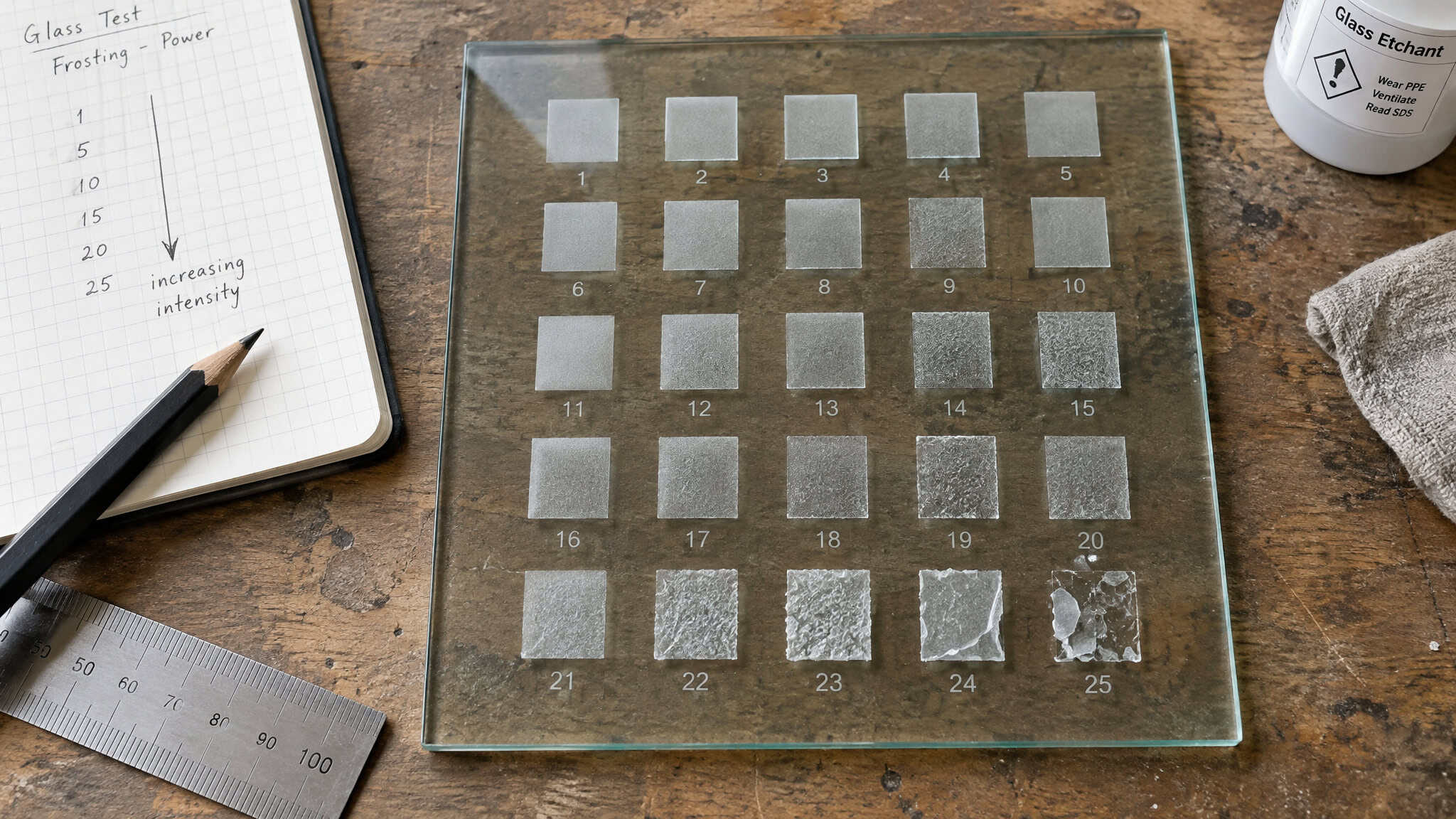
Field note: A winning square only counts if you can reproduce it — record the machine, focus height, and pass count before moving on.
The wattage-scaling failure
Energy per point equals power divided by speed. Double the power at identical settings and you double the energy per point, which is why a 10W recipe scorches on a 20W head. The same pattern plays out every time someone bolts a new 20W diode module onto a machine and watches it scorch wood at old 10W settings. Scale power down in rough proportion before testing.
The unit trap
Diode software displays mm/min while CO2 and fiber controllers use mm/s. 6000 mm/min equals 100 mm/s. Paste an unconverted value across that boundary and you’re off by a factor of sixty, which is the kind of error that eats an entire evening before you figure out what happened. I have spent embarrassing amounts of time on smaller bugs. Divide by 60 before pasting anything.
Here’s the composite failure pattern, a typical first attempt, not anyone’s specific project: a maker copies a forum chart, runs it once, and gets a uniformly wrong result across the whole design. That uniformity is the tell. A patchy result means something else went sideways; a uniformly wrong result points to a recipe that was never right for the machine, tuned to a different wattage, lens, or batch.
The usual mistakes, gathered in one place: copying values between wattages without scaling, mixing up units, engraving out of focus, running one hot pass where two light ones would do, skipping air assist, testing on a different batch, leaving power at 100%, and letting a dirty lens absorb output.
Diode lasers on glass: the wavelength problem and the paper-backing fix
A blue diode cannot mark clear glass directly. The 450nm beam passes through without absorption, so no power setting fixes it, and the working method is paper-backing back-engraving rather than a number you can copy.
Start with the physics, because it prevents the classic “more watts should fix it” mistake. This is a wavelength limit, not a power limit. It’s the same reason a diode can’t cut clear acrylic but handles dark cast acrylic fine: the beam only does work when something absorbs it. Clear acrylic cutting belongs to CO2 machines for the same reason. When a settings chart marks diode as “not suitable” for glass, that entry describes what the beam can be absorbed by, not how many watts you own.
Tribo’s back-engraving method puts white printer paper behind the glass. The 450nm beam passes straight through the glass, burns the paper, and the heat creates subtle microfractures on the far surface. You’re engraving the front of the glass by burning paper behind it.
Cleaned results resemble frosted glass, with a lamp-like light projection through the mark.
The tested numbers: S255/F2000 and S255/F1500 came out nearly smooth, and the top speed tested was 2000 mm/min. DPI wasn’t recorded in the experiment, so I’m saying so rather than inventing it. Note the result is a subtle frosted mark, not a deep etch; this technique lives in a different weight class than a CO2 machine’s frosted work.
Many diode owners hit the same surprise here, in the spirit of that experiment: you aim the diode at clear glass, nothing happens, and the first “success” is accidental. A piece of paper behind the glass burns, and it leaves a frosted-looking mark on the glass above it.
The broader principle: glass needs an absorptive intermediary, whether that’s paint, black cardstock, or marking paper per the wider consensus. Diode glass work is prep-driven, which is why the coating question deserves its own deep dive. If you’re scaling across diode wattages, apply the energy-per-point rule: halve the power expectation when stepping down from 20W to 10W, and convert mm/min to mm/s by dividing by 60 before pasting anything into a CO2 or fiber controller.
Fiber laser glass etching: the foil-and-paint path
Fiber lasers can’t mark clear glass directly either, and the fix is changing what the beam hits, not the parameters. The prep combo, where every detail matters: aluminum foil shiny-side-down on the glass, Prang black paint airbrushed dark, and the lens lowered 7mm out of focus. The community recipes are copy-paste-able starting points: a 30W fiber with a 100x100mm lens runs 100 speed / 90 power / 25 freq / 0.04 line interval, and a 60W MOPA runs 138/75/308/Q-500/0.360 on a 220mm lens.
The framework behind those numbers is four fiber dials doing four jobs: power controls depth, speed affects darkness and exposure, frequency affects smoothness and contrast, and pulse width controls energy distribution. That framework earns its keep across the community recipe library, which is full of staged multi-pass metal workflows like removal, clean, blacken, and polish. Glass is the outlier where the lever isn’t the parameters at all, it’s the target surface.
Choosing the right glass: soda-lime, borosilicate, and why crystal fails
Pick soda-lime glass, meaning bottles, windows, drinking glasses, and mirrors, for the whitest and most forgiving etch.
The glass types
Soda-lime engraves well with a whiter, more opaque result. Borosilicate, the Pyrex and lab-glass family, is more heat-resistant, etches lighter, and may need higher power. Crystal gives a finer but less opaque etch, and large crystal pieces can chip out before any result appears, for the lead-heating reason established earlier. The practical guidance: steer toward soda-lime drinkware, not heirloom crystal. I’m not going to give you crystal “settings,” because the working position is that crystal is effectively not engraveable by CO2 at any useful scale.
Color expectations
The base etch is monochromatic. All shading comes from micro-chipping, which is why raster and binary designs work best and true grayscale fights you. Colored results require ceramic paint applied once the etch is done, or glass formulated to change color. It’s not a settings change, so set this expectation before anyone designs red text on red glass and discovers the laser doesn’t care about their color scheme.
Fixing rough results and staying safe: cleanup, recovery, and glass-specific hazards
A chipped-looking piece can often be saved: buff the loose surface shards away with a Scotch-Brite pad or something similar. jkwilborn prefers steel wool, and his reasoning is worth carrying with you. The shards sit on the surface and slowly fall away over time, often into someone’s finger. That’s the visceral reason to polish rather than handle-and-hope.
For cleanup, remove masking carefully, since fine glass dust clings to it, then wipe or rinse with a soft brush, damp cloth, or dish soap and water. A soft-bristled toothbrush works for intricate details. Don’t scrub aggressively while the etched surface is still fragile.
Safety here is basic competence, not fear: wavelength-rated goggles, fume extraction, and ventilation per OSHA and Laser Institute of America guidance. The glass-specific note is that the hazard is fine dust settling on your optics, not smoke, so ventilation is about protecting your machine and your eyes, not clearing the room.
Laser versus sandblasting: what laser glass marking can and cannot match
Sandblasted or rotary-engraved glass, done properly, is superior in quality. The laser’s frosted mark is surface fracturing, not carved depth, and no settings table changes that. Sandblasted pieces come out clean and smooth, but they demand serious effort, time, and money to get there, and it’s worth being honest that laser salespeople often wear blinders to that quality gap. What lasers win on is cost, speed, flexibility, and forgiveness: most people will happily trade a little quality to save both, and with the right rotary attachment flipping the bottle, you can repeat the etching around the whole piece. So pick the laser for iteration speed and low cost on drinkware and signage, and reach for sandblasting when heirloom-quality depth and smoothness is the requirement.
Frequently Asked Questions
What are the best settings for laser engraving on glass?
For CO2 machines, workable starting ranges run from 100-300 mm/s at 30-50% power on a 40W tube up to 400-800 mm/s at 40-80% on a 100W tube. The counterintuitive rule: as tube wattage climbs, the power percentage you run drops, because energy per point is what governs the result. Treat any chart value as a starting point to validate on your own machine, not a guarantee.
What are the recommended power levels for laser engraving?
On glass, lower than you’d expect. A 40W CO2 tube starts at 30-50% power, while a 100W tube can run as low as 12-15% — one operator engraved an 800x800mm window at just 12-15% power on a 100W tube. Since glass engraving is micro-fracturing rather than material removal, dumping too much energy per point causes chipping, so the fix is less energy per point, never more power.
Why does glass crack or chip when laser engraving at high power?
Because the ‘engraving’ is actually fracturing, not material removal. Trapped air and moisture inside the glass expand when heated, and since glass is rigid, the stress gives way at the surface as microscopic fractures. One hot pass dumps all that thermal stress at once and over-stresses the fracture network — multiple light passes with cooling between them beat a single hot pass every time.
Can you laser engrave glass with a CO2 laser or do you need a fiber laser?
CO2 is the standard for direct glass engraving — it produces the frosted mark through surface micro-fracturing. Fiber lasers can’t mark clear glass directly either; the working method is prep-driven, with aluminum foil shiny-side-down on the glass, black paint airbrushed over it, and the lens run out of focus. Diodes also can’t mark clear glass directly due to wavelength limits, not power limits.