You export the file, load it onto the printer, hit start, and then stand there watching a small box hum to itself. For the first few minutes, nothing looks like a part at all. The bed warms up, the head taps its home switches, a single thin line traces the perimeter, and every pause feels like it might be an error if you don’t know what the machine is doing.
At the hardware level, a 3D printer runs through a tight sequence of physical handoffs: heating up, feeding material, sticking the first layer, cycling through the build, and cooling down so you can remove the finished part. The design-to-slice software chain belongs to the start-at-home workflow; what happens here is strictly the machine side, starting the moment G-code hits the control board. And those quiet opening minutes, before any real geometry even exists, are where the highest failure risk lives.
Key Takeaways
Every 3D print runs the same physical loop: deposit or fuse one thin cross-section, bond it to the layer below, step by one layer height, and repeat across hundreds or thousands of layers.
First-layer bed adhesion is the highest-risk stage of a print because every subsequent layer inherits that initial placement, and a detached perimeter turns into a tangled mess immediately.
Fused Deposition Modeling (FDM), Stereolithography (SLA), and powder bed fusion (PBF) all run that same layer loop, swapping the heat source and feedstock, from open-air melted plastic all the way up to 3,500 W electron beams in a vacuum.
Table of contents
Table of Contents
How a 3D printer builds an object, one loop at a time
A 3D printer builds an object by repeating one physical loop: deposit a thin layer of material, bond it to the layer beneath, step by one layer height, and repeat until every sliced cross-section exists. Unlike subtractive manufacturing, where a mill or lathe cuts material away from a solid block, additive manufacturing builds parts up from nothing, layer by layer. That bottom-up approach means customization doesn’t significantly raise production cost, prototypes and small batches come together fast, and you waste far less material than you would machining the same shape.
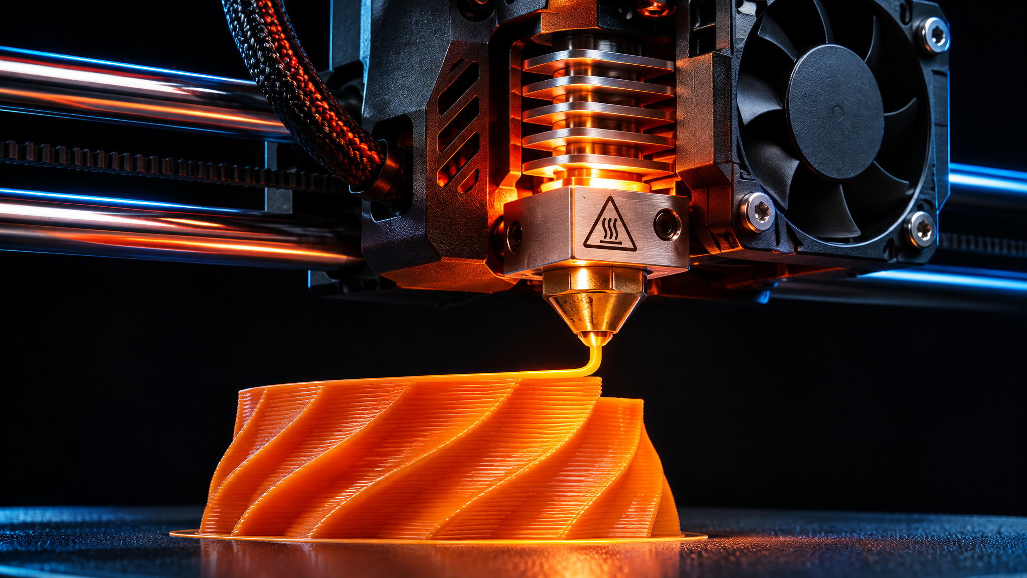
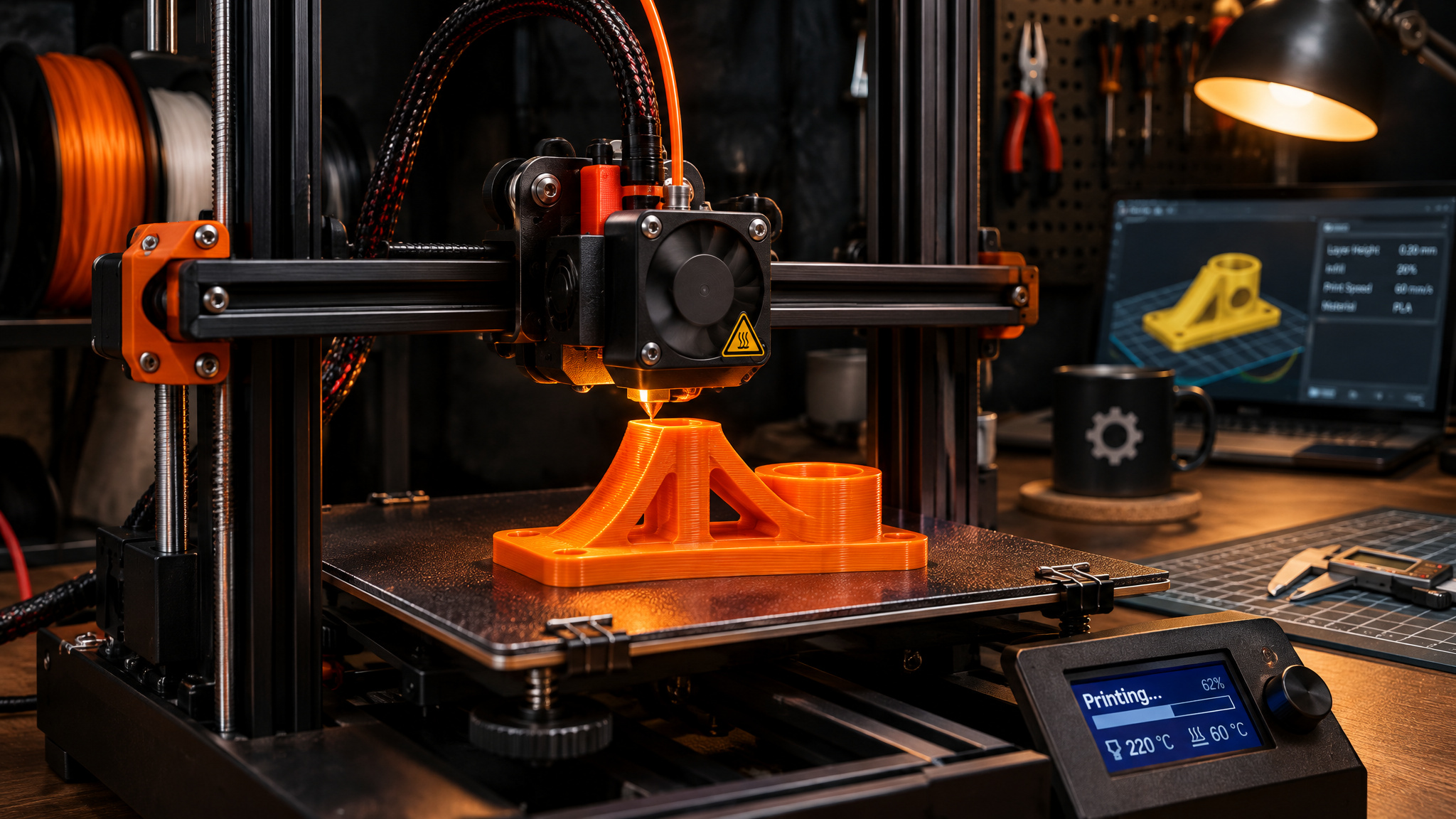
In Fused Deposition Modeling (FDM), the most common desktop setup, the machine melts a solid thermoplastic strand and stacks it in ultra-thin lines, one layer at a time, until the shape is done. Six core components handle the job: a rigid frame, a heated print bed that promotes first-layer adhesion and prevents warping, an extruder that pushes filament, a nozzle that lays down the bead, motors that drive motion, and a control board that coordinates timing.
From digital file to finished part, an FDM print follows this sequence:
- A digital 3D model is created in computer-aided design (CAD) software.
- Slicing software cuts the model into hundreds or thousands of horizontal cross-sections.
- Thermoplastic filament feeds off a spool into the extruder assembly.
- A drive gear grips the filament and pushes it steadily toward the hot end.
- The hot end melts the solid strand into a viscous liquid at its processing temperature.
- The nozzle forces molten plastic onto the build platform as a continuous bead.
- Motors move the print head and bed along the X, Y, and Z axes to deposit each layer.
- Each hot layer bonds to the layer beneath and cools solid before the next pass begins.
- The finished part cools completely and is removed from the build platform.
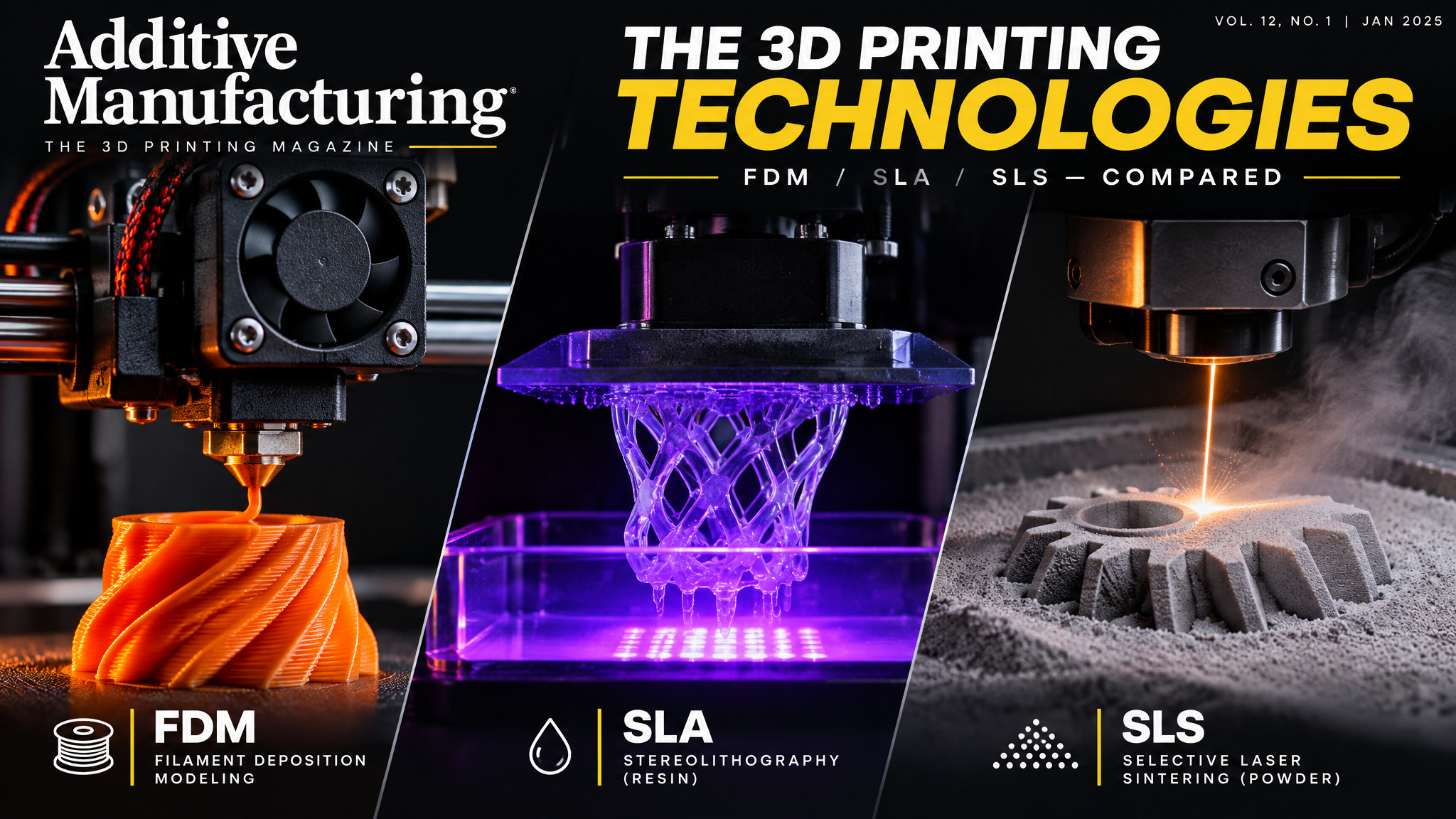
That same repeating loop powers Stereolithography (SLA) and powder bed fusion (PBF) as well. The difference across these machine families comes down to what heat source they use, what material they feed, and what environment sits inside the chamber.
How the printer knows what to print: G-code and axes
By the time a 3D print starts, slicing software has already cut the 3D CAD model into hundreds or thousands of ultra-thin horizontal cross-sections and converted them into G-code. Every perimeter, internal infill pass, support move, and layer height is decided in the slicer before the file ever reaches the machine, which is why an accurate CAD model matters so much, especially for SLA. If you want the full CAD-to-slicer walkthrough, that lives in our start-at-home guide; once the file is loaded, the printer isn’t making geometry decisions anymore.
At the machine level, the printer is strictly an executor running timed repetition. The control board acts as the printer’s brain, reading those digital coordinates and synchronizing heaters, fans, and motion. Motors drive the print head and bed along the X and Y axes to trace each layer’s exact outline, then step along the Z axis by one predetermined layer height after the layer finishes. Holding all of that together is the frame, the structural skeleton that keeps the rails, bed, and gantry rigid so nothing shifts mid-pass.
From spool to nozzle: feeding and melting the filament
Inside an FDM 3D printer, material delivery works as a continuous metering system where feed speed directly controls how much plastic hits the bed. Thermoplastic filament arrives as a continuous solid plastic strand wound on a spool and feeds into the extruder assembly, which is the heart of material deposition.
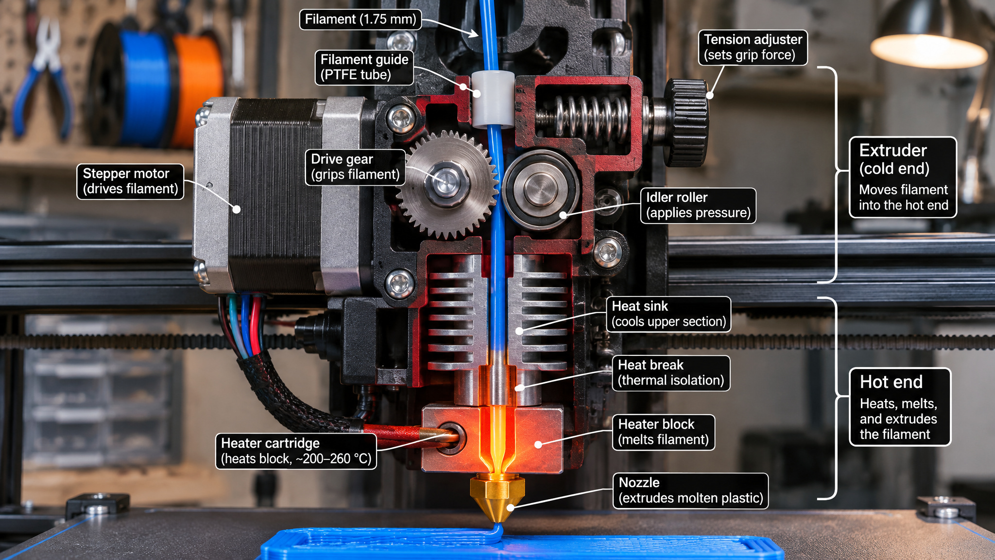
A drive gear inside the extruder grips the filament and pushes it steadily toward the hot end. Inside the hot end, heating and temperature-control components bring the filament up to its required processing temperature, turning the solid strand into a viscous liquid. That molten thermoplastic is then forced through the nozzle, a tiny opening at the tip of the hot end positioned accurately above the build platform before the first layer starts, emerging as a continuous bead. Because deposition rate depends on how fast the drive gear pushes plastic into that fixed-temperature melt zone, any feeding hiccup or temperature swing shows up immediately as a defect in the bead.
Hobby hot ends only need enough thermal energy to melt fed plastic. By contrast, industrial powder bed fusion systems fuse raw powder using 100 to 1,000 W fiber lasers or electron beams running up to 3,500 W.
The first layer: where most prints fail
The heated print bed exists to make the first layers adhere properly and to prevent warping as the plastic cools. On my own machine, bed adhesion is the stage that causes the most failures when it isn’t handled correctly, making those quiet opening minutes the highest-risk stretch of the entire print.
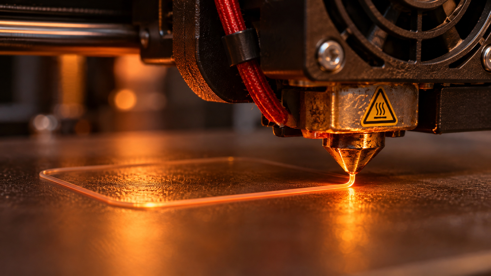
The reason is mechanical inheritance. Every layer in a print sits directly on top of the one beneath it, so the first layer sets the foundation for the whole stack. When the first perimeter fails to stick to the build platform, the nozzle keeps extruding onto detached filament, and the print collapses into a tangled mess before any real geometry even exists. (In powder bed fusion, the build platform plays a slightly different role: it supports and secures the base plate, steps vertically downward after each fused layer, and acts as a heat sink for the fusion energy.)
The layer loop: deposit, bond, cool, repeat
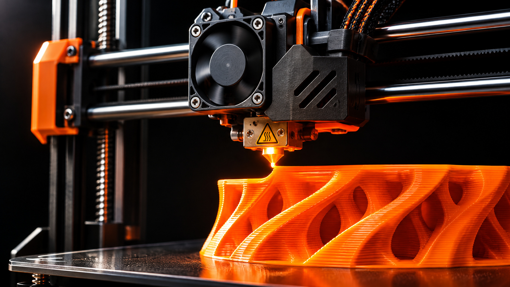
Once the first layer holds, the printer settles into its rhythm. Watching a time-lapse or process video of a print in action makes the cadence obvious: the nozzle lays down hot plastic, that molten bead bonds with the cooler layer beneath, and the plastic rapidly solidifies as it cools. The machine repeats that cycle automatically across hundreds or thousands of layers until the model is complete.
Two physical traits of FDM parts come straight from this hot-bead-on-cold-layer bonding: visible layer lines and direction-dependent, or anisotropic, strength. Because each pass fuses onto a previously cooled surface, parts are naturally weaker between layers than they are along the continuous strands within a single layer. Cooling behavior also ties directly to print speed on tall, thin features, which tend to wobble or bond poorly if the nozzle drops a new hot layer before the previous pass has cooled enough to hold its shape.
Infill and supports: what the machine prints that isn’t the object
The nozzle doesn’t distinguish between the outer shell of your model and the temporary or hidden scaffolding inside it, because both are just pre-sliced paths in the G-code. Internal infill cuts material consumption while still providing the structural strength the part needs from the inside.
Temporary support structures solve a simpler physics problem: the nozzle can’t extrude plastic into thin air. When a model has overhangs or complex geometry, the printer builds scaffolding underneath those areas so the upper layers have something to land on, which often surprises beginners who catch the printer mid-run looking like it’s extruding over empty space. Those supports have to be removed after the print finishes, making support cleanup one of FDM’s main practical drawbacks.
Removing the finished part and why FDM’s limits exist
Once the final layer finishes and the part cools, you remove the completed component from the build platform. FDM earns its spot as the everyday workhorse for rapid prototyping, engineering models, customized tools, and functional parts because of its low cost, simple operation, flexible material options, and efficient material use.
Every major FDM limitation maps back to the mechanics you just watched happen:
| Machine stage | What the printer is doing |
|---|---|
| Load G-code | Control board reads pre-sliced layer coordinates, infill, and supports |
| Heat bed and hot end | Build platform warms to prevent warping; hot end reaches melt temperature |
| Feed and extrude | Drive gear pushes filament into the hot end and out the nozzle |
| Lay first layer | Nozzle deposits the initial perimeter onto the heated print bed |
| Run layer loop | Head traces X/Y paths, bonds hot beads to cool layers, steps Z per layer |
| Cool and remove | Finished part solidifies completely and separates from the build platform |
Those bead-by-bead mechanics explain the trade-offs. Visible layer lines come from the rounded geometry of an extruded bead, direction-dependent strength comes from interlayer bonding, and the post-processing burden comes from breaking away overhang supports. SLA avoids extruded beads, though it trades those issues for resin handling requirements and a narrower set of photopolymer materials.
SLA: the same loop with light instead of heat
Stereolithography (SLA) runs the exact same layer-by-layer loop using light instead of heat. Across the three main 3D printing families, FDM melts thermoplastic filament in open air, SLA cures liquid photopolymer resin with ultraviolet (UV) light inside a vat to create detailed, smooth objects, and powder bed fusion fuses powder with a laser or electron beam in a controlled chamber.
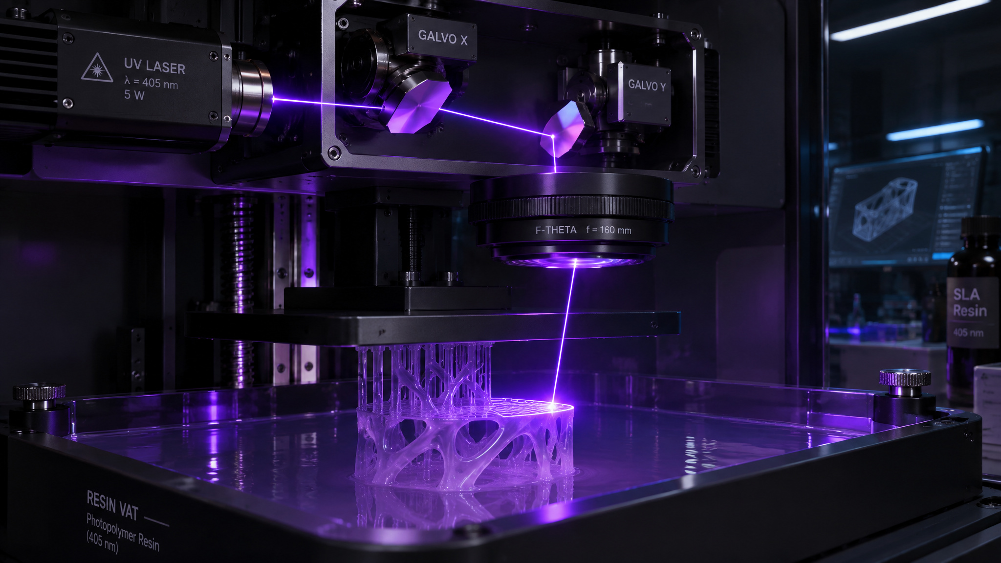
SLA works through photopolymerization, a process where light-sensitive liquid resin solidifies the moment UV light hits it. Inside the machine, a resin vat holds the liquid photopolymer, while a build platform, UV laser light source, scanning system, and control mechanism coordinate each pass. Precision scanning mirrors rapidly steer the UV laser beam across the resin surface to trace one cross-section, turning that exact region solid. After each layer cures, the build platform steps by a predetermined layer thickness so fresh liquid resin covers the build area, and the next layer cures and bonds to the last until the finished part rises out of the vat.
Finishing an SLA print takes three mandatory post-processing steps:
- Wash off the uncured liquid resin clinging to the part.
- Carefully remove the temporary support structures.
- Apply additional UV curing so the resin reaches its final material properties.
Because a laser spot draws finer features than a physical plastic bead, SLA is valued for high accuracy, smooth surfaces, and fine detail in prototypes, dental and medical models, jewelry patterns, and detailed engineering components. Its trade-offs are resin handling, support removal, extra post-processing, and being limited to available photopolymer materials.
Powder bed fusion: SLS, SLM, DMLS, and EBM
Powder bed fusion (PBF) builds objects layer upon layer by fusing loose powder with a laser, known as Laser PBF (LB-PBF), or an electron beam (EB-PBF). The main variants differ by how much heat they put into the powder, partially sintering it or melting it all the way through:
- Selective Laser Sintering (SLS): A trademarked laser process that sinters polymer powders like nylon and polyether ketone ketone (PEKK) for prototypes and durable functional parts with complex geometries.
- Selective Laser Melting (SLM) fully melts powder particles so they solidify into dense layers.
- Direct Metal Laser Sintering (DMLS): A trademarked name for metal 3D printing that uses metal powder and, despite having “sintering” in the name, can also achieve full melting like SLM.
- Electron Beam Melting (EBM): A vacuum process that preheats metal powder to roughly 1,000°C before melting it with an electron beam, cutting residual stresses and distortion, reducing support and stress-relief needs, running faster than SLM or DMLS with better material properties, and requiring metal feedstock because electrons excite metal molecules.
Inside a metal powder bed fusion printer
Each layer starts with powder delivery from a reservoir, either gravity-fed or positioned beside the bed. A powder dispenser moves vertically upward to expose fresh powder while a powder collector moves downward to catch overflow, and a recoater blade sweeps across the build platform (side to side, back to front, or via a pivoted rotating arm) to spread a uniform layer. After each fused pass, the build platform steps down while the build plate acts as a heat sink.
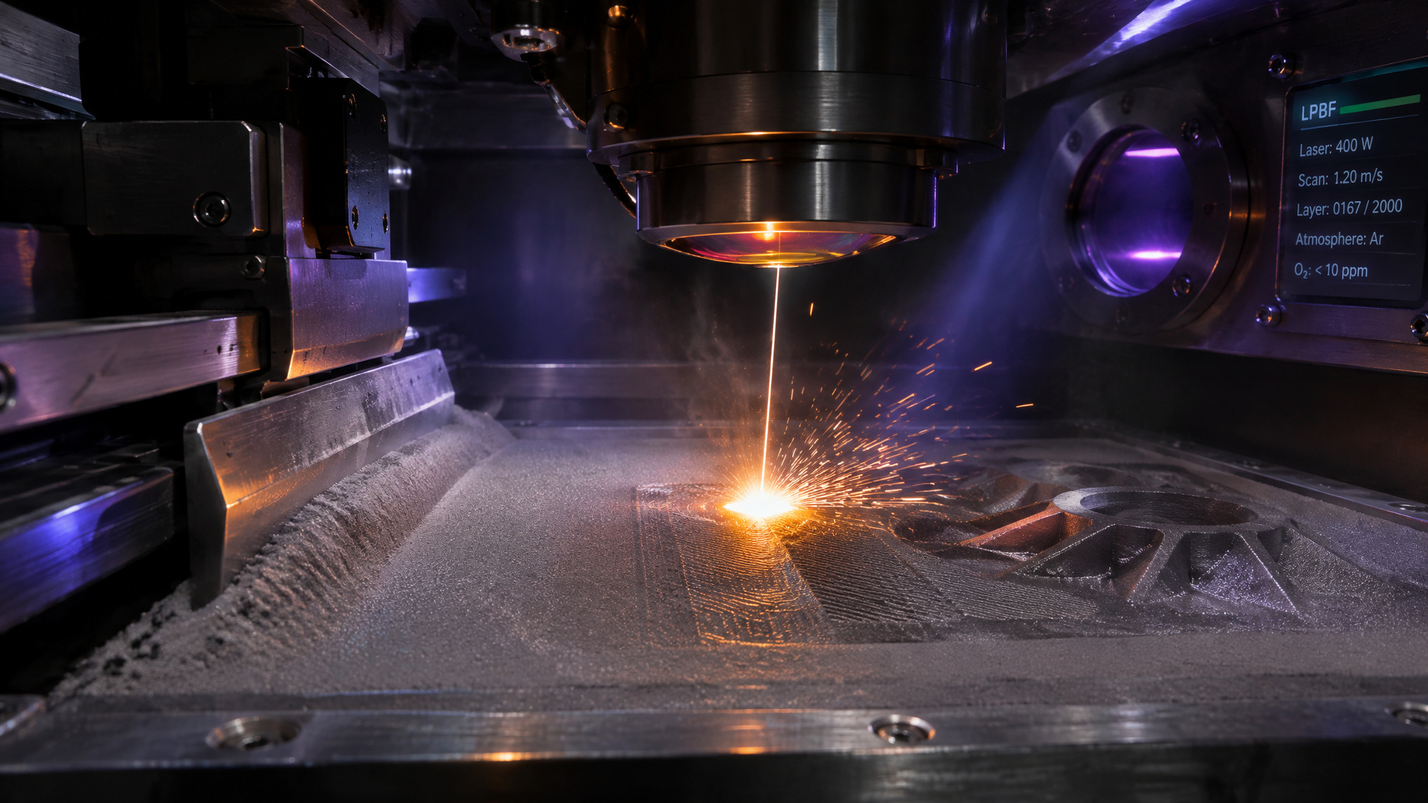
To fuse that layer, LB-PBF machines steer 100 to 1,000 W fiber lasers (continuous, pulsed, or modulated, sometimes in multi-laser arrays) using galvanometer scanners with rotating X and Y mirrors plus collimation and focusing lenses, all inside an inert argon gas flow that prevents oxidation and clears process smoke. EB-PBF swaps the optics for an electron column, tungsten filament, astigmatic focus and deflection lenses, and collimation and focusing lenses delivering up to 3,500 W inside a vacuum chamber equipped with pumps, a leak detector, and control valves so gas molecules don’t scatter the beam or oxidize the hot metal.
What these machines cannot print
What a 3D printer can’t print is set by material and process constraints rather than a fixed list of forbidden objects. SLA can only cure available photopolymers, EBM requires metal feedstock, and steep overhang geometry in extrusion or resin setups requires temporary supports rather than printing unsupported into empty space.
Why the machine side matters now
3D printing is getting more popular, and with AI making it easier than ever to design parts, I think it’ll become a household staple over the next decade. As software tools lower the barrier to generating a 3D model, knowing what happens inside the box (heating, adhesion, deposition, and cooling) is what separates a clean part from a failed print.
That same layer-by-layer loop already powers medical, aerospace, and construction printing as well as desktop prints. Medicine uses it for custom prosthetics, surgical guides, and bioprinted tissues moving toward functional organs for transplantation, while automotive and aerospace teams rely on SLS and DMLS metal printing for rapid prototyping, custom car components, and lightweight aircraft parts. The same additive principle produces architectural models, intricate culinary food designs, entire homes printed in days for housing and disaster relief, and on-demand tools printed by astronauts in space.
Frequently Asked Questions
How does a 3D printer work for dummies?
Instead of carving an object out of a solid block like a mill or lathe, a 3D printer builds things up from nothing, one paper-thin slice at a time. It lays down or fuses a single cross-section of material, bonds it to the layer underneath, steps by one layer height, and repeats that loop hundreds or thousands of times. Whether it’s melting plastic filament, curing liquid resin with UV light, or zapping powder with a laser, the core trick is stacking thin slices until a solid part emerges.
How does a 3D printer work step by step?
First, you create a 3D model in CAD software and run it through a slicer, which chops the shape into thin horizontal cross-sections and outputs G-code instructions. On a standard desktop FDM machine, the bed and hot end warm up, a drive gear pushes plastic filament off a spool into the melt zone, and the nozzle traces the first perimeter onto the build platform. From there, motors move the head and bed along the X, Y, and Z axes to lay down, bond, and cool each successive layer until the finished object cools off and comes off the plate.
What do you need to operate a 3D printer?
On the digital side, you need a 3D model—created in CAD software—and slicing software to translate that geometry into G-code coordinates the machine can follow. On the hardware side, you need the printer itself along with the right feedstock for its process, such as thermoplastic filament on a spool for FDM, liquid photopolymer resin for SLA, or loose polymer or metal powder for powder bed fusion. Once the file hits the control board, the machine handles the heating, motion, and timing on its own.
What things cannot be 3D printed?
There isn’t a neat blacklist of forbidden objects—what you can’t print comes down to material and physics limits. SLA machines can only cure compatible photopolymer resins, while electron beam melting (EBM) requires metal feedstock because the electron beam has to excite metal molecules. Geometrically, extrusion and resin printers also can’t print steep overhangs out into empty air; without temporary support scaffolding underneath, the material has nowhere to land.
What are the disadvantages of using a 3D printer?
In desktop FDM printing, the bead-by-bead mechanics leave behind visible layer lines and anisotropic strength—meaning parts are noticeably weaker between layers than along a single continuous strand. You also have to deal with post-processing, like snapping off temporary overhang supports, and bed adhesion failures that can turn the opening minutes of a print into a tangled mess. Switching to SLA smooths out those layer lines, but you trade them for messy resin handling, mandatory washing and UV curing steps, and a smaller pool of photopolymer materials.
What happens inside a 3D printer during a print, from heating to finished part?
Once G-code lands on the control board, the printer becomes a strict executor: it warms the build platform and hot end, homes its axes, and feeds material through the extruder and nozzle to lay down the critical first perimeter. After that foundation sticks, the machine settles into a repeating cadence of tracing X and Y paths, bonding molten plastic onto the cooled layer below, and stepping the Z axis by a single layer height. When the final cross-section is done, the whole part cools down so it solidifies completely before you remove it from the bed.
What are support structures in 3D printing and when are they needed?
Support structures are temporary scaffolding that the printer builds underneath steep overhangs or complex geometry so upper layers have a surface to land on. Because a nozzle can’t extrude molten plastic into thin air, the slicer automatically writes support paths into the G-code right alongside your actual part. They aren’t part of the final object, so you have to break or clean them away after the print finishes—making support removal one of the main practical headaches of FDM and SLA printing.
What is slicing software and what does it do before a 3D print starts?
Slicing software is the translator between your 3D CAD model and the printer’s control board. Before the machine ever heats up, the slicer chops the digital model into hundreds or thousands of horizontal cross-sections and converts them into G-code. Every outer perimeter, internal infill pattern, support path, and layer height is locked in at that stage, so once you hit start, the printer isn’t making any geometry decisions on its own.
What is the difference between FDM, SLA, and powder bed fusion 3D printers?
All three run the same layer-by-layer loop, just with different materials, energy sources, and build chambers. FDM melts solid plastic filament through a hot nozzle in open air, while SLA uses a UV laser and scanning mirrors to cure liquid photopolymer resin inside a vat. Powder bed fusion steps up to industrial territory, using 100 to 1,000 W fiber lasers in argon gas or electron beams up to 3,500 W in a vacuum to fuse loose polymer or metal powder.