Two identical-looking 7.62 mm circles can leave LightBurn, enter SheetCam, and meet completely different fates depending on the file extension. On February 14, 2024, at 5:15 a.m. on forum.sheetcam.com, user bLouChip asked why people say SheetCam prefers DXF over SVG after importing SVG files for about two years without trouble, until 7.62 mm circles suddenly failed full circle recognition.
Zooming in on the SVG circles revealed a tiny 0.038 mm vertical segment at the 3 and 9 o’clock positions joining the top and bottom hemispheres, while the DXF circles had none. SheetCam’s 0.2 mm Circle recognition limit setting only governs drilling, which accepted the shape, leaving Path Rules to reject it.
Similar geometry surprises hit laser-cut box files. On March 21, 2021, user fleckrj noted that entering a gauge’s exact material thickness with 0 kerf in a parametric box generator like Tabbed Box Maker lines up tab and slot widths. Yet the tabs still run too long, and keyed divider holes come out right in width but too tall (a May 29, 2021 commenter, lisahagan30, also hit a download snag on that thread). Choosing between SVG and DXF for a laser-cut box comes down to which format your specific exporting application emits cleanly for your CAM parser.
Key Takeaways
Exporting 7.62 mm circles as SVG from LightBurn v1.5.01 into SheetCam v7.1.35 introduced 0.038 mm vertical seam segments at 3 and 9 o’clock because SVG approximates circles with bezier curves, while DXF export preserved true circles across every operation.
Your exporting app dictates the best file format: SheetCam developer Les_Newell recommends exporting SVG from Inkscape because of its history of DXF export bugs, and sticking with DXF from LightBurn and CAD tools.
Re-importing the same vector sign into Vectric VCarve showed that SVG preserved connected vectors across three named layers (frame, welcome, and swirl), DXF kept all non-empty layers with a slight downward placement shift, and PDF collapsed unconnected vectors onto a single layer.
Table of Contents
What SVG and DXF store: beziers vs true arcs
DXF (Drawing Exchange Format) and SVG (Scalable Vector Graphics) are both vector formats that map directly to laser cutting because the laser traces paths, with DXF storing true arcs and circles natively while SVG stores circles as bezier curves that only approximate a circle. Vector work built in tools like Inkscape fits laser cutting for the exact same reason: you think in paths, and the machine follows paths.
SheetCam developer Les_Newell diagnosed the circle import failure by noting he suspects LightBurn outputs SVG circles as bezier curves. That creates a translation problem at the machine layer. G-code can’t represent bezier curves directly, so CAM software like SheetCam tries to fit those bezier curves to circular arc segments and falls back to converting them into short straight lines when they don’t match cleanly.
Raster formats are for engraving, not cutting
Raster formats like PNG, JPG, and BMP work for laser engraving because the machine scans pixel images back and forth instead of tracing continuous vector paths for a cut.
When SVG circles stop being circles: the 0.038 mm seam
SVG circles from some exporters are bezier approximations rather than true circles, causing CAM software like SheetCam to insert tiny straight line segments that fail strict circle-recognition checks when exported from LightBurn, whereas DXF preserves true circle geometry. While choosing between SVG from graphic editors and DXF from CAD tools depends on your software, machine, and how a project was built, DXF is the safer bet when downstream CAM rules demand exact engineering geometry.
In a February 14, 2024 thread on forum.sheetcam.com (across posts at 5:15 a.m., 3:10 p.m., and 4:31 p.m.), user bLouChip documented this exact bug with 7.62 mm diameter circles exported from LightBurn v1.5.01 into SheetCam v7.1.35. Those holes failed the Path Rules “on small circle” qualification as SVG, yet passed every circle check when exported from LightBurn v1.5.01 as DXF.
What makes that case such a great piece of workshop forensics is the timeline. The user had run SheetCam for roughly two years, importing SVG files almost exclusively under the reasonable philosophy that if a workflow isn’t broken, you don’t fix it. Then a routine job with 7.62 mm holes behaved strangely. During an Inside Offset Operation, SheetCam recognized the SVG shapes as circles for placing a leadin arc at the circle center, and a Plasma Drill Operation also recognized them as circles. Yet the “on small circle” Path Rule ignored them completely.
Inspecting the imported SVG geometry in detail exposed the exact culprit. At the 3 and 9 o’clock positions on the 7.62 mm holes, where the top and bottom hemispheres met, the SVG import contained a vertical straight line segment measuring 0.038 mm. Because LightBurn v1.5.01 wrote the SVG circles as bezier curves and SheetCam v7.1.35 had to approximate where the curve didn’t quite fit an arc, those two microscopic vertical flats broke the true-circle geometry.
When the user exported the exact same 7.62 mm circles from LightBurn v1.5.01 as a DXF file and brought that DXF into SheetCam v7.1.35, the 0.038 mm vertical segments at 3 and 9 o’clock vanished. SheetCam recognized the DXF imports as true circles in every operation, including Path Rules. Suspecting a newer LightBurn version had changed how SVG circles were written, bLouChip switched to DXF imports going forward. Whenever a CAM tool mysteriously rejects a hole, zooming in on the 3 and 9 o’clock cardinal points for tiny straight-line seams turns a baffling software quirk into an obvious bezier artifact.
Why the same file passes one check and fails another
SheetCam evaluates circle geometry with two completely different strictness thresholds for center-point drilling and Path Rules, which is why DXF imports pass every Path Rule check where SVG imports fail. In CAM workflows, file reliability depends on how the exporting app writes curves and how strictly the receiving operation checks them: a collision of software defaults we love dissecting here at GeekExtreme. In SheetCam v7.1.35, importing 7.62 mm circles from LightBurn v1.5.01 produced a split result across operations:
- Plasma Drill Operation: SVG import passed circle recognition; DXF import passed circle recognition.
- Inside Offset Operation (leadin arc at circle center): SVG import passed circle recognition; DXF import passed circle recognition.
- Path Rules (“On circles” / “on small circle” qualification): SVG import failed due to 0.038 mm vertical segments at 3 and 9 o’clock; DXF import passed as a true circle.
That split happens because SheetCam’s internal geometry checks are intentionally asymmetric. As developer Les_Newell explained in the thread, the “On circles” Path Rule is strict: it requires the imported geometry to be a true circle, or circular arcs that lie exactly on a circle. Even a 0.038 mm straight segment between hemispheres disqualifies the path from being a true circle.
Drilling hole-center recognition is built to be far more forgiving. When SheetCam looks for a hole center for a Plasma Drill Operation or a center leadin arc, it accepts anything roughly circular. That’s also why the user’s attempt to troubleshoot via SheetCam’s preferences hit a wall. SheetCam has a setting called Circle recognition limit, which was set to 0.2 mm in bLouChip’s setup.
A 0.038 mm seam is well under 0.2 mm, so it looks like the software should accept the circle everywhere. However, as the setting’s quick help implies and Newell confirmed, the 0.2 mm Circle recognition limit applies purely to drilling operations. It has zero effect on Path Rules. You can crank that 0.2 mm drilling limit as high as you want, and a bezier-approximated SVG circle with 0.038 mm hemisphere seams will still fail the “On circles” Path Rule every single time.
The arc fitting tolerance trap
To fix laser-cut holes that fail circle checks or turn into short straight segments, switch the export format to DXF at the source instead of loosening import tolerances. SheetCam does offer an arc fitting tolerance setting under Options -> application options -> drawing import that can coax SVG bezier curves into arcs.
When G-code conversion forces SheetCam to approximate SVG bezier curves, bumping up that arc fitting tolerance under Options -> application options -> drawing import gives the importer more leeway to snap nearly circular bezier segments into circular arcs instead of dropping in short straight lines.
It’s a tempting knob to twist, and Les_Newell pointed it out as a possible adjustment, but with a sharp warning: increasing the arc fitting tolerance hides the underlying geometry problem rather than fixing it, and it can reduce the accuracy of your resulting toolpaths. Exporting as DXF instead of SVG fixes the curve translation cleanly and keeps toolpath precision intact across the rest of your part.
What each format preserves on import: the VCarve round-trip test
When a vector file imports with shifted placement, collapsed layers, or broken paths, the culprit is the specific export format’s container behavior: in Vectric VCarve, SVG preserves connected vectors and named layers, DXF preserves non-empty layers with a slight downward placement shift, and PDF drops unconnected vectors onto a single layer requiring the Join Vectors tool.
In a hands-on demonstration using Vectric VCarve (a direct-purchase program that runs offline without an internet connection), speaker Garrett took a welcome sign project built months earlier with a custom font, framework, and bitmap-traced swirls (sold as a DXF on Etsy alongside an email list offering free file downloads and a 50 to 60 word “words that sell” list). VCarve exports to SVG, PDF, DXF, AI, and EPS, and Garrett exported the sign as “welcome training” in the three formats most people use: DXF, SVG, and PDF. None of the imported vector files carry toolpaths, so you always build your own toolpaths after import for full control.
| Format re-imported into VCarve | Preserves original layers | Vectors arrive connected | Work surface placement |
|---|---|---|---|
| SVG | Yes (3 named layers: frame, welcome, swirl) | Yes | Matches original |
| DXF | Partial (all except empty layer zero) | Yes | Partial (slightly lower on work surface) |
| No (merges into 1 single layer) | No (requires Join Vectors tool) | Matches original |
Color and layer conventions: every tool ships its own defaults
Layers cut in the wrong order or at the wrong power when a file moves between laser programs because color-to-process layer mapping is a per-tool default rather than a universal standard, while SVG stroke-width conventions (such as hairline cut rules) depend on your specific CAM documentation rather than these color-layer workflows. On a laser-engraved wooden box from design file to finished cut, those color-as-process layers control power, speed, and cut sequence.
LaserWorks, RDWorksV8, and LaserGRBL color defaults
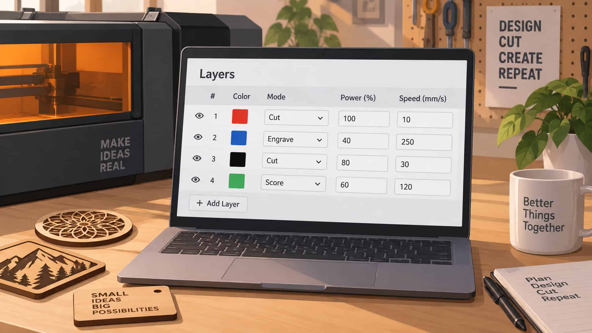
LaserWorks defaults to black lines for cutting and blue lines for scanning/etching. RDWorksV8 defaults to red for cutting and blue for scanning (double-clicking a layer changes its processing mode). LaserGRBL filters only four colors (red, blue, black, and green) to segment layers, using red for cutting and blue for engraving.
Why layer color sets power and speed
Scan and engrave layers run at low power and fast speed, while cut layers require high power and slow speed, tuned by experimenting per machine, material, and thickness. In RDWorksV8 on 1/8 inch birch, a scan layer runs at min/max power 30 and 350 mm/s speed, while a cut layer runs at min/max power 80 and 10 mm/s speed. RDWorksV8 projects save locally as .ld via File > Save As and push to the laser’s memory via Download after naming the file, which throws a communication error if disconnected.
LaserGRBL setups on a 12-watt Crowy Falcon cutting a 300 x 300 mm document on 3 mm base wood use Configured Document for offsets and alignment and Framing for live placement. On a job with a red exterior business card rectangle and a blue interior pentagon, the red cut layer runs at 100% power and 300 mm/min, the blue engrave layer runs at 4,000 mm/min with S min 0 and S max 40%, and a black layer uses a 20% power reduction for shallower depth.
Cut order: inner shapes first
In RDWorksV8, a DXF logo built in Carve Pro imports via File > Import to get layer settings and saves as initials_logo on the desktop. In LightBurn, Optimization Settings under Windows > Cuts govern cut sequence (Order by Layer, Order by Group, Order by Priority, cutting inner shapes first, direction order, and removing overlapping lines), with Tools > Preview verifying the run.
The LaserWorks DXF workflow and its version trap
Opening DXF files in the Hatch Education laser cutter workflow requires LaserWorks version 5 rather than version 8, and finished jobs must be exported to USB via Save to U file instead of the regular save command.
Walking through the Christmas decoration fan tail project shows how LaserWorks v5 handles DXF geometry and cut sequencing in practice. The imported decoration started at 53.78 mm tall with a 5 mm x 4 mm hanging hole, with the outer circles set to black for cutting and the inner pattern set to blue for etching. To turn the outer profile into a true 80 mm circle, you unlock the aspect-ratio padlock in LaserWorks and type 80 into one dimension, then resize the hanging hole down to 3 mm.
Imported DXF patterns often arrive as dozens of loose paths: the decoration’s ungrouped bird pattern showed up as roughly 100 separate elements until Edit > Group collapsed it into one selectable unit. Finally, Edit > Set Cut Property locks in the cut order so the small inner circle cuts first, the bird second, and the outer circle last, keeping the part anchored in the stock before saving via Save to U file.
Why this matters for laser-cut boxes
Laser-cut box files are packed with finger joints and hole circles for hardware or mounting, meaning bezier-approximated SVG circles and 0.038 mm seam artifacts can trip circle-based CAM rules, even though the link between SVG curve approximations and physical kerf and finger joint fit is reasoned from SheetCam’s circle-recognition failure rather than directly measured in box-fit tests. When sizing those project holes, 3 mm usually fits a key ring, 5 to 6 mm fits ribbon, and jewelry holes belong near the top edge.
DXF from LightBurn, SVG from Inkscape: the exporter rule
Neither SVG nor DXF is universally better for laser cutting; the reliable format is determined by the application exporting the file, making SVG the right choice when exporting from Inkscape and DXF the better choice when exporting from LightBurn. While the general rule of thumb treats SVG as standard for graphic design editors and DXF as standard for CAD tools, SheetCam developer Les_Newell points out that your exporting application’s quirks matter most: Inkscape has a history of DXF export issues so you should export SVG from Inkscape, whereas LightBurn v1.5.01 exported true circles to SheetCam v7.1.35 via DXF while its SVG output produced bezier approximations (as Newell advised, if DXF works better for your workflow, stick with it).
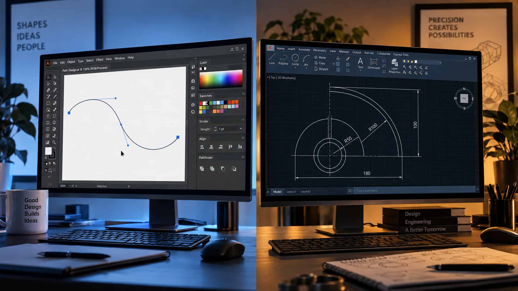
Importer support also changes over time. Newell noted that SheetCam’s SVG import was historically a bit buggy, but these days it’s pretty solid, and SVG also cleanly preserved the frame, welcome, and swirl layers in VCarve.
Getting clean exports from Inkscape
To export an Inkscape file into LaserGRBL without missing elements, convert text via Path > Object to Path (otherwise text vanishes in LaserGRBL, and it imports as outlines unless filled), vectorize raster images with Trace Bitmap (Edge detection, Brightness cutoff, or Color quantization), apply a rounded Fillet (Inkscape) via Corners and Path Effects, and run the Hatch Fill extension (0.25 mm spacing works well) for filled engraving.
LightBurn and the free alternatives: formats, cost, and setup
Picking between LightBurn’s $60 all-in-one suite and a free Inkscape-plus-LaserGRBL stack comes down to your operating system, budget, and controller setup.
What LightBurn imports and what it costs
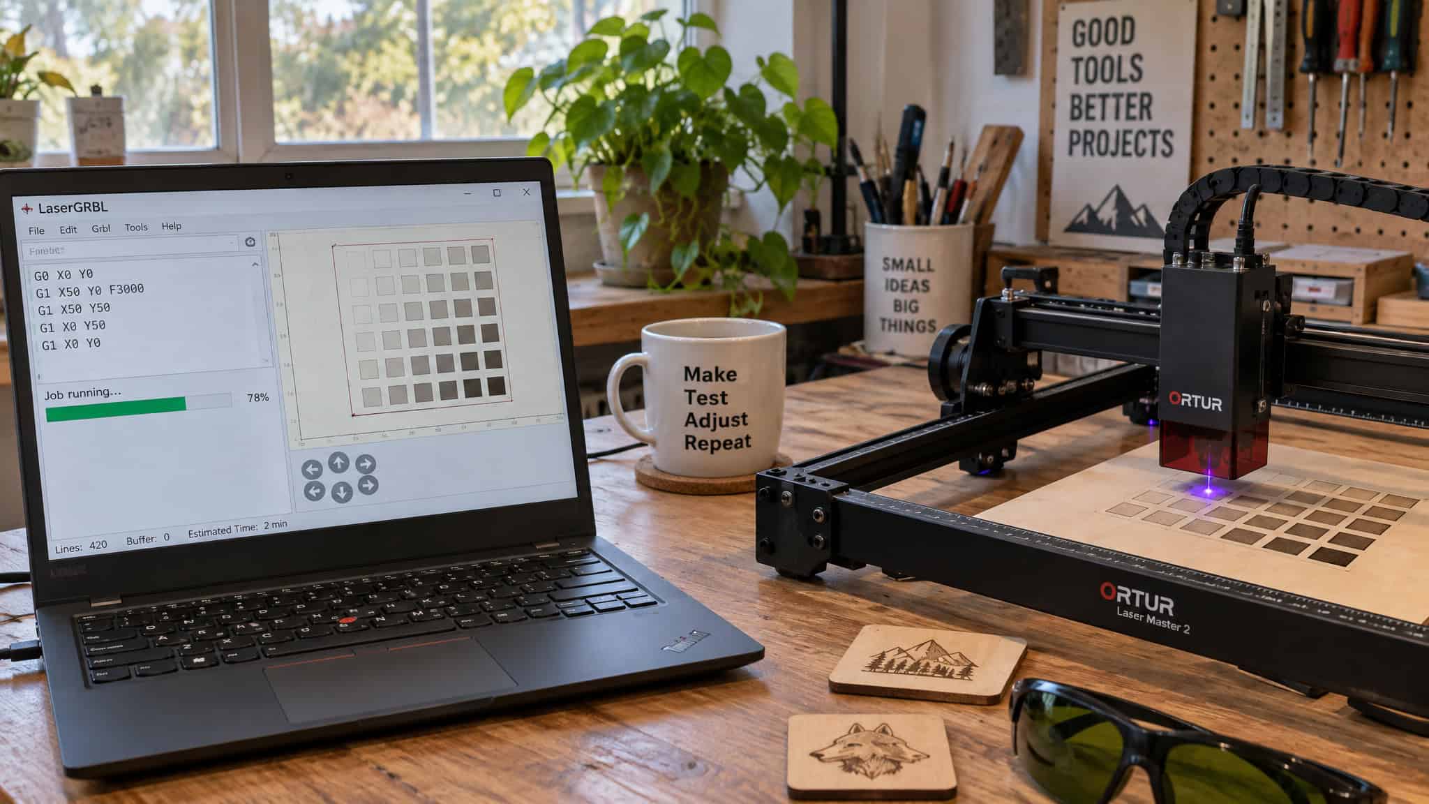
Per the MakeUseOf LightBurn guide, LightBurn supports six import formats. AI, DXF, PNG, JPG, BMP, and SVG, across Windows, macOS, and Linux, and costs a $60 one-time fee with a 30-day free trial downloadable from the J Tech Photonics website.
Connecting LightBurn and setting the origin
LightBurn connects to lasers over Ethernet/UDP (using an IP address), Serial/USB, or Packet/USB, and provides four origin options: Rear Left, Rear Right, Front Left, and Front Right. The MakeUseOf general-audience guide notes that G-code machines like Marlin or Shapeoko should choose From Left as the origin and machines with limit switches and homing support should enable Auto 'home' on startup, though those settings may not generalize to every machine.
The free path: Inkscape and LaserGRBL
For hobbyists on Windows who want a zero-cost workflow before paying $60 for LightBurn or buying offline software like Vectric VCarve, combining Inkscape with Windows-only LaserGRBL gives you a completely free, open-source vector design and G-code sender stack.
Working with imported files in LightBurn: raster, image modes, and settings
Photos and raster files (PNG, JPG, BMP) import into LightBurn via File > Import or Ctrl + I, where you tune engraving parameters in Shape Properties (Windows > Shape Properties if hidden) and set speed and power in the Cuts/Layers panel.
LightBurn’s seven image modes
- Threshold: already-dithered images.
- Ordered: simple unshaded images.
- Dither: photos and smooth-shaded images.
- Atkinson: smooth-shaded solid-colored images.
- Jarvis: best high-quality realistic photo dithering.
- Newsprint: high-DPI dither for Smoothie controllers.
- Grayscale: 3D engraving.
Because speed and power vary by material, run test cuts and check Tools > Preview before firing the laser.
Frequently Asked Questions
When should I use SVG instead of DXF for laser cutting files?
Use SVG whenever you export designs from Inkscape, which SheetCam developer Les_Newell points out has a track record of DXF export bugs. SVG is also the superior choice when re-importing projects into Vectric VCarve, where it keeps connected vectors intact across named layers like frame, welcome, and swirl without shifting their placement on the work surface.
Why are my laser cut layers cutting in the wrong order or wrong power setting?
Every laser program uses its own proprietary color-to-process defaults instead of following a universal standard. For instance, LaserWorks maps black lines to cutting and blue to etching, while RDWorksV8 and LaserGRBL use red for cutting and blue for scanning or engraving. To keep parts from dropping out of the stock mid-job, you also have to configure cut sequencing inside your target software—such as enabling “cutting inner shapes first” under LightBurn’s Optimization Settings or using Edit > Set Cut Property in LaserWorks v5.
