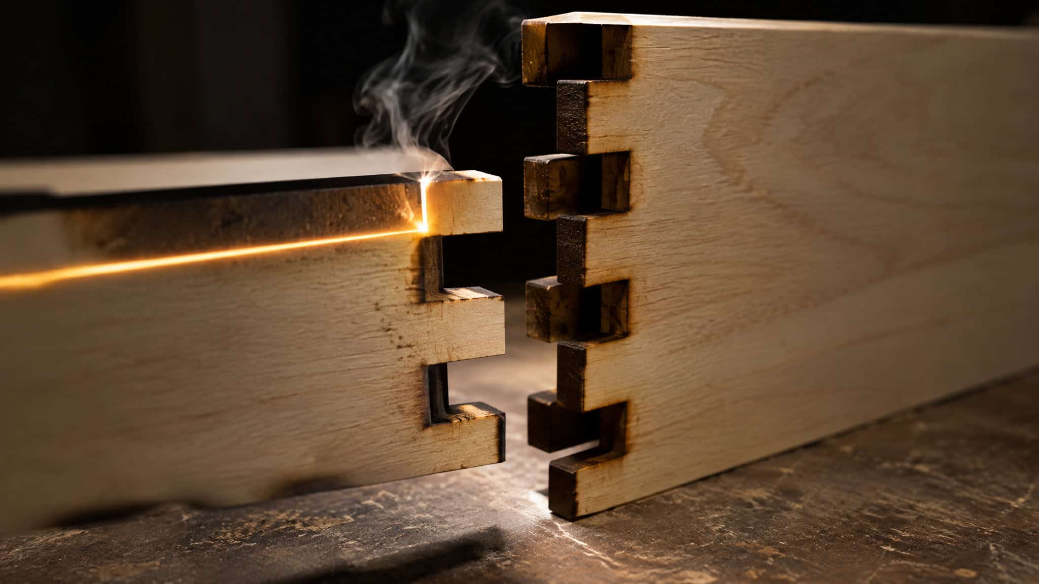
A box joint file that looks mathematically perfect on screen comes off the laser bed loose, wobbly, or welded tight because laser-cut box joints (finger joints), laser kerf, and actual material thickness collide in the physical cut. Joint fit is a mechanical tolerance and design problem rather than a machine settings problem. Just like in 3D printing and CNC routing, no universal magic kerf number exists: you have to measure and design for the specific laser, focal length, power setting, and sheet stock sitting on your bench.
Key Takeaways
Cutting a 20 mm test square that measures 19.85 mm on digital calipers reveals a 0.15 mm total kerf, which you divide by two to get a 0.075 mm per-side offset for LightBurn.
Parametric tools like OpenSCAD extensions and the Inkscape tabbed box maker beat static CAM offsets when swapping stock because they tune slot width directly to caliper-measured material thickness.
Finger joints need a minimum 10 mm width so wood fibers don’t flex under pressure, and a snug pressure fit (such as a 0.75 mm outward offset on French cleats or 0.08 mm on MDF) avoids cracking warped box walls.
Table of Contents
What laser kerf is
Laser kerf is the material removed by the cutting tool, just like the slot left by a table saw, bandsaw, or router bit, and it forms because the beam passes through the focus lens and CO2 laser nozzle or air assist cone in an hourglass shape. Even when the tightest focal point sits around 0.08 mm, the real cut is generally wider and the walls are never a perfect 90 degrees because the slight bevel shifts with focal point height. Running a deliberately out-of-focus cut on wood makes that vaporized channel obvious, showing why makers measure kerf per setup instead of trusting a lookup table.
Why laser cut box joints don’t fit as drawn
Laser-cut box joints (finger joints) fail to fit as drawn because laser kerf removes material on both sides of the vector path while sheet stock rarely matches its nominal thickness. Ignoring kerf lets the beam vaporize material from both mating edges, leaving uncompensated finger joints loose by roughly twice the per-side kerf, and a second error stacks on top when slots are drawn to nominal store-bought thickness instead of caliper-measured thickness.
If your setup has a 0.075 mm per-side kerf, every mating finger and slot interface loses about 0.15 mm of wood. Getting a joint to hold isn’t just about cutting inside, on, or outside the vector line: the slot width has to match the actual thickness of the sheet in your hands and the tightness you want. Standalone cutouts rarely care about that loss, but precision fits like box joints, puzzle pieces, and inlays depend on it, and the exact gap shifts with material thickness, focal point height, and beam divergence from entry to exit.
How to measure kerf with a test cut and calipers
- Laser kerf measurement workflow: Cut a known-size square and halve the caliper-measured shortfall to find your per-side offset.
- Cut a test coupon: Run a standard 20 mm x 20 mm or 1-inch x 1-inch square on your project stock and mark its X and Y axis orientation before lifting it.
- Measure with metal digital calipers: Check the cutout across both axes (for example, a 20 mm square measuring 19.85 mm on X and Y).
- Calculate total kerf and per-side offset: Subtract the 19.85 mm measured size from the 20 mm drawn size for 0.15 mm of total kerf, then divide by two for a 0.075 mm per-side offset.
- Cut a 20 mm x 20 mm or 1-inch x 1-inch square on your real project stock.
- Mark the X and Y axis orientation before lifting the piece from the bed.
- Measure the cutout with metal digital calipers and subtract the measured size from the drawn size.
- Divide the total shortfall by two to get your per-side kerf offset.
The test cut workflow step by step
Mark which way the square sat on the bed before you pop it out, because some lasers and sheet goods cut differently along the X and Y axes. Metal digital calipers beat plastic ones here for consistency and accuracy, and built-in unit switching between millimeters and decimal or fractional inches saves manual math.
Two worked examples
On the YouTube channel Keep Making, a 20 mm test square measured 19.85 mm on both axes, yielding 0.15 mm total kerf and a 0.075 mm per-side offset for LightBurn. In an imperial test across five 1-inch squares on a diode laser with a rectangular beam focus, widths ran 0.996 to 0.994 in and heights ran 0.993 to 0.992 in, averaging 0.9936 in for a 0.0064 in total kerf and a 0.0032 in per-side offset (multiply inches by 25.4 to get about 0.081 mm).
Averaging, labeling, and the divide-by-two trap
Plywood hides soft spots, hard spots, air gaps, and extra internal glue joints, so average across multiple cuts, use colored layer lines to kiss-cut or engrave labels in the same job, and tape the pieces in order. Always divide your caliper shortfall by two: the caliper reads kerf loss from both opposite edges of the square, so entering the full shortfall doubles the compensation and swings the joint from loose to impossibly tight.
Applying the kerf offset in LightBurn
LightBurn’s kerf offset is a layer-level setting in your CAM (computer-aided manufacturing) software that shifts cut paths outward automatically once you enter your per-side value. Before running test cuts, zero out any existing layer offset first, and check that your imported vectors are closed polygons. If an imported file contains open vector paths, LightBurn’s kerf offset silently does nothing until you close the nodes with Edit > Auto join selected shapes.
- Open the Cuts / Layers window in LightBurn and double-click your cut layer.
- Zero out any existing Kerf Offset before cutting measurement coupons, then enter your measured per-side value as an outward offset for the real build.
- Run
Edit > Select open shapeson imported geometry to catch unjoined paths. - Use
Edit > Auto join selected shapesso LightBurn can tell the inside of the part from the outside.
Where the offset goes and how to prep
LightBurn keeps kerf compensation inside the layer settings rather than forcing you to redraw your vectors, and an outward offset is what expands fingers and tightens slots for box joints. When you cut your initial measurement coupons, make sure any existing kerf offset on that layer is set to zero or your caliper numbers will lie to you. You also need to run the exact tested power and speed settings you plan to use on the final box, because slower or hotter passes cause extra burning that widens the cut and skews the measurement. Maker Vintauri demonstrated this exact LightBurn layer workflow on an Acer P20 Pro laser.
The closed-shape failure mode
The classic trap when importing SVG or DXF box files is unjoined geometry. LightBurn can only calculate which direction is outward or inward when a vector forms a completely closed perimeter. If an imported tab profile is actually a collection of disconnected line segments, the kerf offset setting fails silently and cuts right down the center of the line, convincing makers that kerf compensation is broken when their shapes were just open.
Running Edit > Select open shapes highlights the culprits immediately, and Edit > Auto join selected shapes welds the nodes shut so the offset works. Letting CAM software shift the toolpath inside or outside the line is much cleaner than nudging lines by hand in CAD: one Alibre Design user manually offsets drawings by a few thousandths of an inch to compensate for kerf, and Keep Making drafts vectors in Rhino3D, but even CAD veterans note that toolpath-level inside/outside kerf control is superior, a feature Glowforge forum users have long wished Glowforge’s cloud software would add.
Parametric design vs CAM offset for joint fit
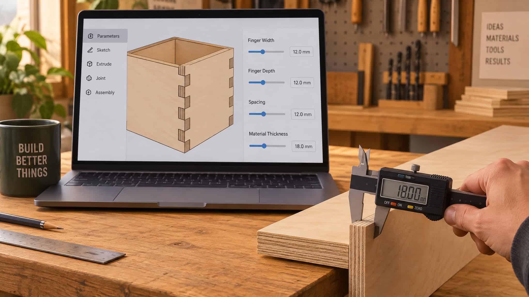
Parametric design beats a static CAM kerf offset whenever you swap materials because parametric files make slot width a tunable variable inside the geometry rather than a global machine offset you have to re-measure per job. Sheet goods sold under the same nominal thickness vary significantly from sheet to sheet, which breaks a uniform line offset that shifts outer edges and inner slots by the same amount. Parametric generators like OpenSCAD extensions and the Inkscape tabbed box maker let you dial slot width directly to caliper-measured stock thickness and target tightness across a Glowforge, a CNC router, or a 3D printer.
Where the tolerance should live
A CAM layer offset in LightBurn shifts every vector on that layer by the exact same distance. That fixes the width of the laser beam, but it can’t rescue a joint when your next sheet of nominal 3 mm plywood measures 2.85 mm or 3.15 mm on the calipers.
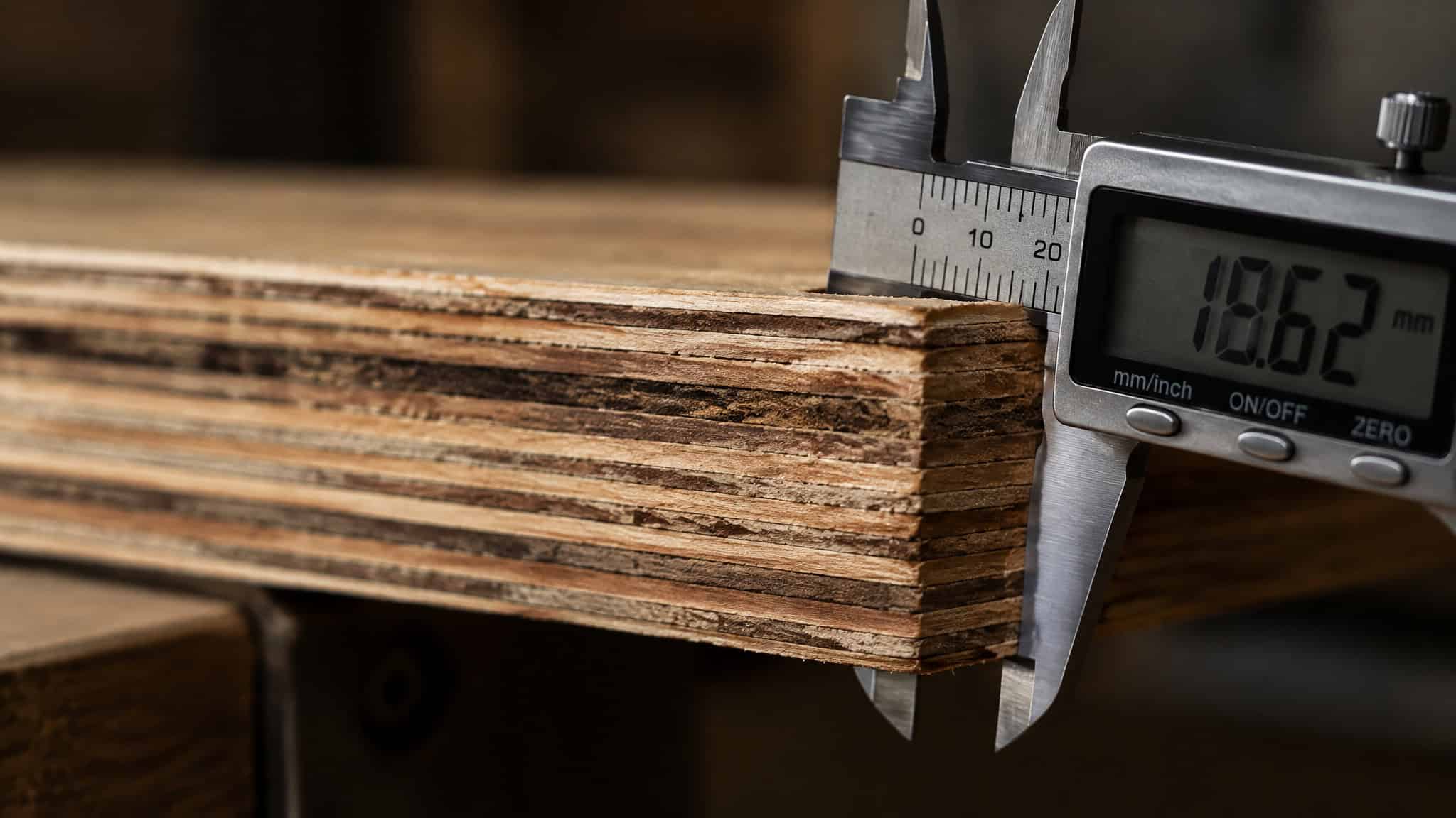
Making slot width an explicit parameter in the design file separates the thickness of the mating board from the width of the fingers, keeping the file portable across machines even though you still have to caliper-test the real sheet on your bench. At GeekExtreme, we look at fabrication files the same way we look at code: hardcoding magic numbers into a machine profile breaks the moment the hardware environment shifts, whereas passing material thickness as a parameter keeps the build portable.
The named tools
For makers who want automated, kerf-aware slot sizing without writing CAD constraints from scratch, the Inkscape tabbed box maker (found under the Extensions menu) and OpenSCAD extensions are the best box joint generators because they pair free software with direct control over material thickness and kerf variables. One Glowforge user even wrote a custom OpenSCAD extension just to rule out third-party box generator bugs after tabs came out too loose. If you already know your exact kerf number and just want a fast browser export, makeabox.io handles the math automatically, while Rhino3D and Alibre Design suit makers who want full manual CAD control over custom features like pin joints and lid clearances.
| Tool | Automated Box Generation | Built-in Kerf & Slot Parameterization | Manual Custom Geometry Control |
|---|---|---|---|
| Inkscape tabbed box maker | Yes (via Extensions menu) | Yes (automates kerf-aware slots) | Yes (editable vector paths after generation) |
| OpenSCAD extensions | Yes (scripted generator) | Yes (tunable slot width and tightness parameters) | Yes (full programmatic CAD control) |
| makeabox.io | Yes (browser-based export) | Yes (auto-calculates once kerf is known) | No (fixed generator templates) |
| Rhino3D | No (manual vector drafting) | Partial (manual or parametric CAD setup) | Yes (full control for custom pins and lids) |
| Alibre Design | No (manual CAD drafting) | Partial (requires manual thousandths-of-an-inch drawing offsets without CAM support) | Yes (full mechanical CAD control) |
Fit targets: glue-up fit vs friction fit
The difference between a glue-up fit and a friction fit in laser-cut joints is a tolerance window of just a couple thousandths of an inch separating a zero-clearance joint that needs adhesive from a glueless press fit that locks by mechanical resistance alone. For press fits, tolerances are subtle: a couple thousandths of an inch is the difference between a zero-clearance glue-up and a glue-free friction fit. If your project uses glue, a slightly loose fit is fine and kerf compensation may not matter at all, especially when you angle parts during insertion after a quick pre-assembly cleaning and dry-fit check.
The offset ladder from a real test
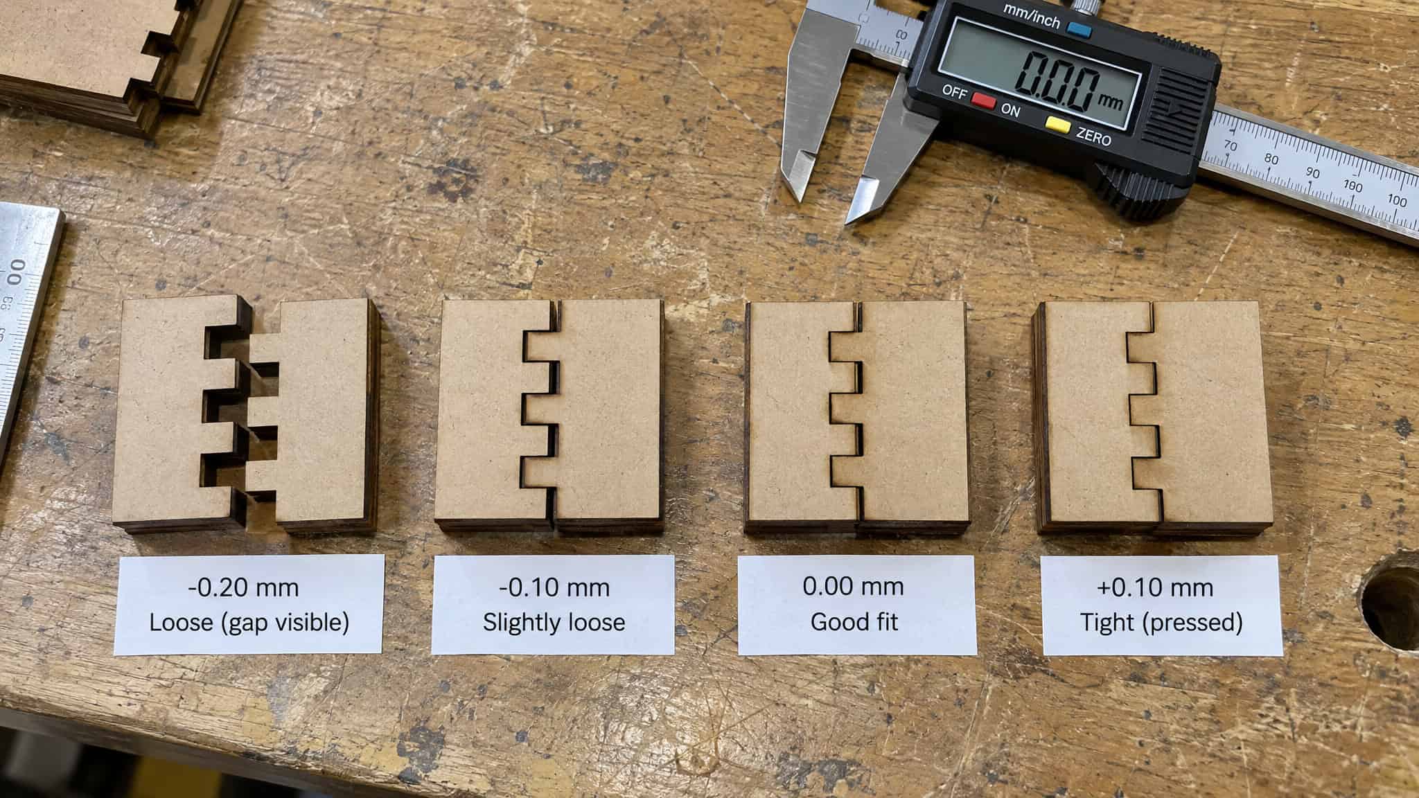
To take the guesswork out of friction fits, the creator at Neat French Cleat cuts four pairs of 6 mm x 6 mm mini box joints in under a minute (included with most of their plans) across an outward offset ladder:
0 mmoffset: loose, wiggles with a visible gap, no holding power at all.0.5 mmoffset: less movement, but still falls apart on its own.0.75 mmoffset: requires a push by hand and holds firmly without being overly tight, making it the creator’s preferred outward curve offset in LightBurn for French cleats.0.1 mmoffset: clicks together gluelessly as a very tight fit, though wood warping makes 0.75 mm the smarter choice on full builds.
Other benches land on different numbers because machines and stock differ: Big Blue Laser Designs hit glueless MDF box joints at 0.08 mm, Keep Making tested 0.07 mm, 0.075 mm, and 0.08 mm on MDF before picking 0.08 mm, and Vintauri used 0.008 in (about 0.2 mm) in LightBurn so joints snapped together without the light-leaking gap that ruins inlays, gears, and long box spans.
Snug beats max-tight
Chasing the tightest possible click fit on a two-tab test piece backfires on a full box. An enclosure has dozens of fingers fighting your assembly force at once alongside natural wood twist and warp, so an overly tight offset risks cracking the box walls or chipping wood fibers during dry-fit; aim for a snug pressure fit instead.
Finger and slot geometry rules beyond kerf
The minimum finger width for a glueless pressure-fit box joint is 10 mm (or at least equal to the material thickness), a structural rule that keeps individual wood tabs from flexing or slipping when pinched by adjacent fingers. Getting kerf right only solves half the mechanical equation; the dimensions of the fingers, slots, and pins decide whether the assembled box sits flat and holds together.
Finger width and length rules
Keep every finger at least 10 mm wide, or as wide as the stock is thick, because narrower fingers give way under lateral pressure from neighboring tabs and skew your fit results. Match finger length to your actual material thickness so the outside faces meet flush without fingertips poking past the corners.
Why the same file fits two thicknesses
In a test across 1/8-inch and 1/4-inch MDF, a cut file tuned for a snug glueless fit on 1/8-inch MDF still assembled gluelessly when cut on 1/4-inch MDF, with the thicker fingers simply protruding past the outside corners (and a file drawn for ~0.11 in stock similarly fits 0.125 in stock without touching the fingers). Finger width cuts predictably and tolerates stock thickness changes; only enclosed slots must be resized when thickness changes because the mating sheet has to slide directly inside the slot opening.
A worked box build: pins, bottoms, and lids
Keep Making demonstrated these geometry rules on a glueless 3 mm MDF box (90 x 70 x 70 mm internal dimensions, two A sides, two B sides, an interlocking bottom, and a pull-up lid that survives a tap test with zero glue). When you’re designing and cutting a laser-engraved wooden box, resizing corner fingers by the 0.075 mm kerf value on both edges and adjusting finger length by that same 0.075 mm keeps the corners dead flush.
For the bottom plate, pin joints beat edge fingers: place the mortise holes at least 3 mm up from the bottom edge, shrink the holes by the kerf value, and expand and lengthen the pins to 10.16 mm wide (for a 10 mm hole) and 6.15 mm long (spanning two 3 mm wall layers plus kerf) with a 0.5 mm bottom fillet to guide insertion. For the pull-up lid, offset the 70 x 70 mm internal insert 0.5 mm inward so moving parts never jam, with an outer rim offset of 3.075 mm (stock thickness plus kerf).
Material variance and the limits of your kerf number
Every kerf number you measure is a single-sheet starting point because natural wood variance, axis-specific beam profiles, and sheet-to-sheet thickness shifts guarantee that materials will drift between runs. Even after you lock in your LightBurn layer or parametric variables, the physical stock on the honeycomb bed gets the final vote.
Grain, axis, and sheet-to-sheet variance
Wood grain and internal material inconsistencies alter kerf consistency by changing how much material the beam vaporizes across soft spots, dark grain bands, air gaps, and internal glue pockets while releasing fiber tension that warps the cut part. Because plywood, solid hardwood, and MDF behave differently under the beam, one maker whose box generator cut top and bottom edge tabs way too loose suspected kerf shifts between soft and dark grain layers (an unverified hunch from a small wood supply rather than a confirmed software bug). More with wood, but even acrylic can vary between sheets that are nominally the same size, and Glowforge forum members still debate whether identical material and settings yield slightly different dimensions across runs or stay constant until settings change.
The traditional woodworking escape hatch
Traditional woodworking compensates for material thickness variation after glue-up by cutting slots slightly deep and sanding the protruding tabs flush, whereas laser design tries to engineer the error out digitally before the cut starts. Because a laser cuts finger widths predictably and repeatedly, that pre-cut precision battle is almost entirely about getting the slot width right for the sheet in front of you.
When you can skip kerf correction
A long-running Glowforge community thread shows plenty of makers getting acceptable box joints with zero explicit kerf correction, either because wood glue bridges the gap or because their project tolerances and material luck were forgiving. If a consistent stock line like Glowforge’s Proofgrade material never varied in thickness, a static file could fit every time, and forum users have floated the idea that laser software might someday let designers tag slot vectors to auto-size to the sheet on the bed. Until software does that automatically, a parametric slot width paired with a 60-second test cut is the workflow that actually holds together.
Frequently Asked Questions
Why do my laser cut box joints not fit as drawn?
Two physical errors stack against a mathematically perfect vector file: the laser beam vaporizes material along both mating edges, and store-bought sheet stock rarely matches its nominal label thickness. Because both sides of the cut lose material, uncompensated joints end up loose by roughly double your per-side kerf—for instance, a 0.075 mm per-side kerf strips 0.15 mm of wood from every mating interface. If your slots are also drawn to nominal thickness rather than caliper-measured stock thickness, the fit falls apart completely.
How do you measure laser kerf using digital calipers for wood projects?
Cut a known test coupon—such as a 20 mm x 20 mm or 1-inch x 1-inch square—on your actual project stock using your final power and speed settings, making sure to mark the X and Y axis orientation before lifting it from the bed. Measure the cutout with metal digital calipers and subtract that reading from the drawn dimension to find the total material lost across both opposite edges. Because plywood has internal glue pockets and density shifts, average several test squares and divide that total shortfall by two to get your per-side kerf.
How does parametric design compare to a CAM offset for laser cut joint fit?
A CAM layer offset in LightBurn shifts every line on a layer by the same fixed distance, which handles beam width but fails when your next sheet of nominal 3 mm plywood measures 2.85 mm or 3.15 mm. Parametric designs make slot width an independent variable tied to your caliper-measured board thickness, separating the depth of the slots from the width of the fingers. We treat fabrication files like code: hardcoding magic numbers into a machine profile breaks when the stock changes, whereas passing thickness as a parameter keeps the file portable across lasers, CNC routers, and 3D printers.
What is the best laser cut box joint generator for a precise fit?
The Inkscape tabbed box maker (located in the Extensions menu) and scripted OpenSCAD extensions are the strongest choices because both are free and let you tune slot width and kerf variables directly to your caliper measurements. If you already know your exact kerf number and just need a quick browser export, makeabox.io automates the math using fixed templates. Makers who want manual CAD control over custom features like pin joints or lid clearances typically draft in Rhino3D or Alibre Design.
What is the minimum finger width for a glueless pressure fit box joint?
Keep every finger at least 10 mm wide, or at least equal to your material thickness. Narrower tabs flex or slip under lateral pressure from adjacent fingers, which ruins a glueless friction fit. You should also match finger length to your actual measured board thickness—plus a per-side kerf adjustment if you are tuning manually—so the outer corners meet flush without protruding.
What are traditional woodworking methods for compensating for material thickness variation?
Traditional woodworkers bypass pre-cut thickness math by cutting box joint slots slightly deep, gluing the enclosure together with the tabs sticking out past the corners, and sanding the protruding fingers flush afterward. Laser cutting flips that workflow by trying to engineer the exact fit digitally before the beam ever fires. Since a laser cuts finger widths with high repeatability, your pre-cut precision work comes down to sizing enclosed slot openings to match the exact sheet on your bed.
